
A welding slit detection device utilizing an X-ray machine

A technology for welding gaps and detection equipment, which is applied in the direction of measuring devices, instruments, scientific instruments, etc., can solve problems such as difficult and accurate detection, and achieve the effects of high precision, simple device structure, and comprehensive detection range

Pending Publication Date: 2018-04-17
东莞市二郎神影像设备有限公司
View PDF0 Cites 1 Cited by
  • Summary
  • Abstract
  • Description
  • Claims
  • Application Information

AI Technical Summary

Problems solved by technology

There may be some quality problems during the welding process of the battery, mainly including the step difference between the end cover and the shell, and the gap between the end cap and the shell that does not meet the requirements. Influenced by the positioning accuracy of the battery during the detection process, it is difficult for the existing technology to accurately detect the above parameters and achieve the purpose of eliminating defective products

Method used


Image

  • A welding slit detection device utilizing an X-ray machine
  • A welding slit detection device utilizing an X-ray machine

Examples


Embodiment Construction

[0020] The following will clearly and completely describe the technical solutions in the embodiments of the present invention with reference to the accompanying drawings in the embodiments of the present invention. Obviously, the described embodiments are only some, not all, embodiments of the present invention.

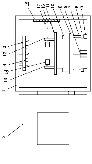
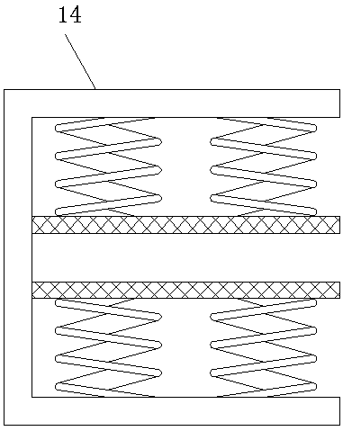
[0021] refer to Figure 1-2 , X-ray machine welding gap detection equipment, including a box body 1, an opening is provided on the side wall of the box body 1, and a box door 2 is hinged at the opening of the box body 1, and the box door 2 is hinged on the box body 1 through a hinge At the opening of the side wall, the door 2 is provided with an observation window, the observation window is made of opaque tempered glass material, and rubber rings are arranged around the observation window, a support frame 3 is installed on the inner wall of the top of the box body 1, and the lower surface of the support frame 3 X-ray tube 4 is installed, and X-ray tube 4 is provided ...


PUM


Abstract

A welding slit detection device utilizing an X-ray machine is disclosed. The device includes a tank body. One side wall of the tank body is provided with an opening. The opening of the tank body is hinged with a tank door. The top inner wall of the tank body is provided with a support. The lower surface of the support is provided with X-ray tubes. The inner wall of the bottom of the tank body is provided with an annular track. Two mobile gears are movably mounted in the annular track, and are at two sides of the annular track. Tops of the mobile gears are welded to supporting bars. A supporting plate is fixed between the two supporting bars. The middle of the inner wall of a bottom plate of the tank body is provided with a first motor. The tail end of an output shaft of the first motor isconnected to the supporting plate. The device is simple in structure, novel in design, high in precision and low in error, can rapidly determine whether a welded part has a slit or not through the X-ray tubes. The device allows a battery to be radiated by X-ray comprehensively and evenly so that the detection structure is more precise and a detection range is more comprehensive.

Description

technical field [0001] The invention relates to the technical field of gap detection devices, in particular to X-ray machine welding gap detection equipment. Background technique [0002] An X-ray machine is a device that generates X-rays. It is mainly composed of an X-ray tube, an X-ray machine power supply, and a control circuit. The X-ray tube is composed of a cathode filament, an anode target, and a vacuum glass tube. The X-ray machine power supply It can be divided into two parts: high-voltage power supply and filament power supply. The filament power supply is used to heat the filament. The high-voltage output terminals of the high-voltage power supply are respectively clamped at both ends of the cathode filament and the anode target to provide a high-voltage electric field to accelerate the flow of active electrons on the filament. The anode target forms a high-speed electron flow. After bombarding the anode target surface, 99% of it is converted into heat, and 1% is ...

Claims


Application Information

Patent Timeline
Patent Type & Authority Applications(China)
IPC IPC(8): G01N23/00
CPCG01N23/00G01N2223/629G01N2223/6462G01N2223/1016
Inventor 李树军
Owner 东莞市二郎神影像设备有限公司
Learn More