
An ion implantation device and its control method

An ion implantation device and an ion implantation technology are applied in the field of ion implantation device and its control, and can solve the problems of decreasing number and high number of impurity particles P on a substrate to be implanted for the first time

Active Publication Date: 2020-02-28
BOE TECH GRP CO LTD +1
View PDF4 Cites 0 Cited by
  • Summary
  • Abstract
  • Description
  • Claims
  • Application Information

AI Technical Summary

Problems solved by technology

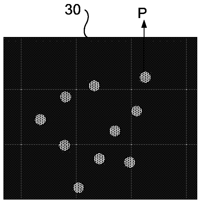
Judging from the current monitoring data, as long as the ion implantation equipment performs the Mass Search process, there is a problem that the first sheet of impurity particles P on the substrate to be implanted is relatively high. With the progress of the ion implantation process, the remaining impurity particles P on the substrate to be implanted The number of

Method used


Image

  • An ion implantation device and its control method
  • An ion implantation device and its control method
  • An ion implantation device and its control method

Examples


Embodiment Construction

[0032] The following will clearly and completely describe the technical solutions in the embodiments of the present invention with reference to the accompanying drawings in the embodiments of the present invention. Obviously, the described embodiments are only some, not all, embodiments of the present invention. Based on the embodiments of the present invention, all other embodiments obtained by persons of ordinary skill in the art without making creative efforts belong to the protection scope of the present invention.

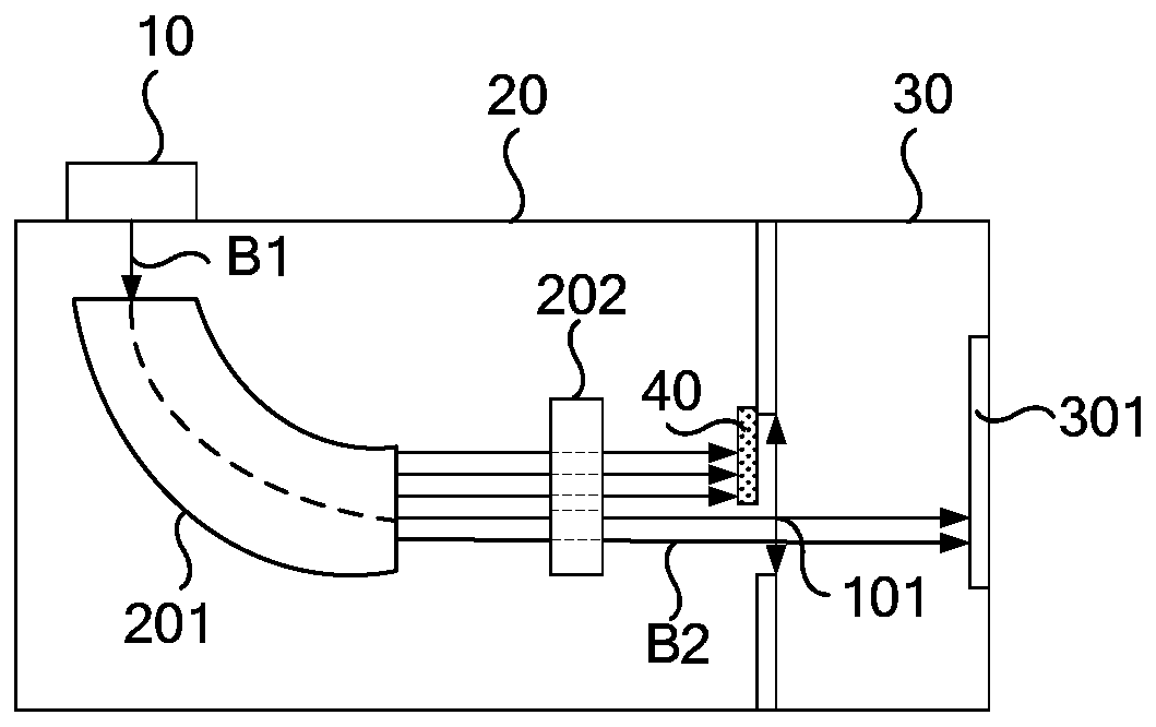
[0033] An embodiment of the present invention provides an ion implantation device, such as figure 2 As shown, it includes an ion source 10 , a beamline device 20 , an ion implantation chamber 30 , and a monitoring device 301 located in the ion implantation chamber 30 . The monitoring device 301 is used to monitor the current of the ion beam B2 entering the ion implantation chamber 30 through the beam line device 20 during the stage of adjusting the magnetic fie...


PUM


Abstract

Embodiments of the invention provide ion injection equipment and a control method thereof, relate to the technical field of display, and can reduce the quantity of impurity particles entering an ion injection chamber generated by inner and outer wall collision of ion beams and an analysis magnetic field in a stage of adjusting the magnetic field strength of the analysis magnetic field. The ion injection equipment comprises an ion source, a beam line apparatus, an ion injection chamber, and a monitoring apparatus positioned in the ion injection chamber; the monitoring apparatus is used for monitoring the current of the ion beams entering the ion injection chamber through the beam line apparatus in the stage of adjusting the magnetic field strength of the analysis magnetic field of the beamline apparatus; the ion injection equipment also comprises an adjustment part for adjusting the opening degree of an ion beam inlet; the adjustment part is arranged in the position of the ion beam inlet of the ion injection chamber; and the adjustment part is used for sheltering the part of the ion beam inlet of the ion injection chamber in the stage of adjusting the magnetic field strength of theanalysis magnetic field of the beam line apparatus.

Description

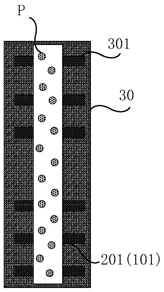
technical field [0001] The invention relates to the field of display technology, in particular to an ion implantation device and a control method thereof. Background technique [0002] The ion implantation equipment (Ion Doping System) will automatically extract the ion beam (Ion Beam) before ion implantation. In the process of ion beam automatic extraction, it is necessary to adjust the magnetic field strength of the beamline device's analytical magnetic field (Beam Line) to determine the optimal magnetic field strength of the analytical magnetic field. This process is also called the Mass Search process. Specifically, the magnetic field strength of the analytical magnetic field is continuously changed, and by such as Figure 1a The shown monitoring device 301 monitors the current (Beam Current) of the ion beam to determine the optimum magnetic field strength. Under the action of the analysis magnetic field 201 with the optimum magnetic field strength, the ion beam can ent...

Claims


Application Information

Patent Timeline
Patent Type & Authority Patents(China)
IPC IPC(8): H01J37/317H01J37/02H01J37/08H01J37/244
CPCH01J37/023H01J37/08H01J37/244H01J37/317
Inventor 李儒健傅永义谭超经好刘晨亮张新慧罗康
Owner BOE TECH GRP CO LTD
Learn More