Electric motor and its manufacturing method

A technology for electric motors and housings, which is applied in the field of electric motors and their manufacturing, and can solve the problems of output (poor power density, small heat exchange area, excessive temperature rise, etc.), to reduce dynamic power, reduce manufacturing costs, and reduce flow resistance Effect

Active Publication Date: 2020-04-10
LG MAGNA E POWERTRAIN CO LTD
View PDF1 Cites 0 Cited by
  • Summary
  • Abstract
  • Description
  • Claims
  • Application Information

AI Technical Summary

Problems solved by technology

[0013] However, in the above-mentioned conventional electric motor, since the spiral path of the cooling fluid is formed around the casing, the heat exchange area between the cooling fluid and the casing is relatively small, and the improvement of the cooling performance is limited.
[0014] Therefore, there will be a problem that the temperature of the stator and / or the rotor will rise too high, so that the output (power density) will relatively deteriorate
[0015] Also, the cooling path is formed in such a way that the spiral tube is inserted into the casing to make the cooling water flow, and the wall thickness of the casing is thus thickened
As a result, the apparent size and weight of the casing increased significantly
[0016] Furthermore, it is difficult to manufacture the motor in such a manner that the helical tube is inserted into the case, thereby causing a problem of increased manufacturing cost

Method used


Image

  • Electric motor and its manufacturing method
  • Electric motor and its manufacturing method
  • Electric motor and its manufacturing method

Examples


Embodiment Construction

[0092] Now, specific embodiments of the present invention will be described in detail with reference to the accompanying drawings. As much as possible, the same reference numerals will be used to designate the same or like parts throughout the drawings, and descriptions thereof will be replaced with the first description. Expressions in the singular include plural concepts unless the context clearly differs. Also, in the disclosed embodiments of the present invention, detailed descriptions of known elements or functions are omitted if they are considered to unnecessarily obscure the subject matter of the present invention. In addition, it should be understood that the drawings are only for easy understanding of the embodiments of the present invention, and thus the embodiments are not limited by any details of the drawings.

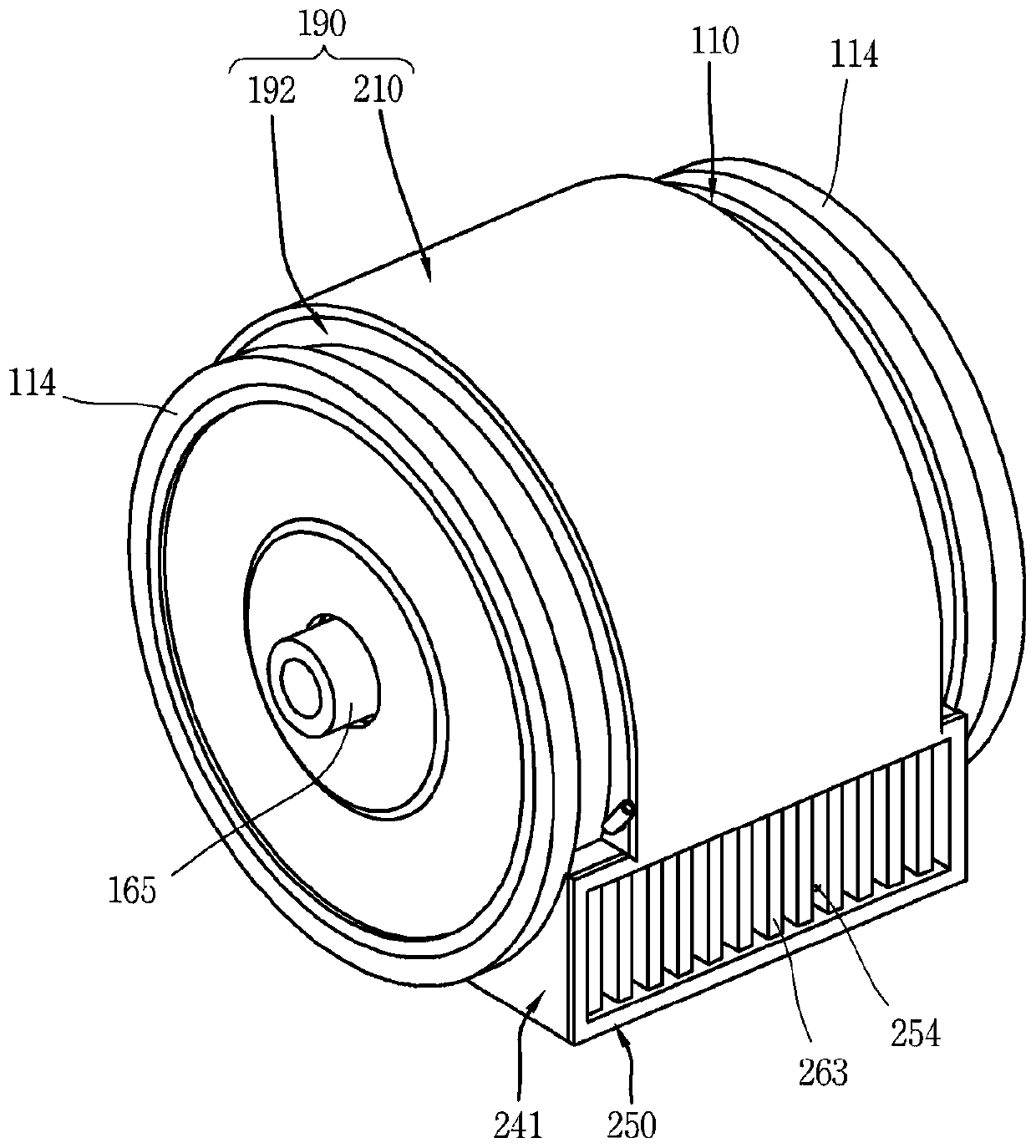
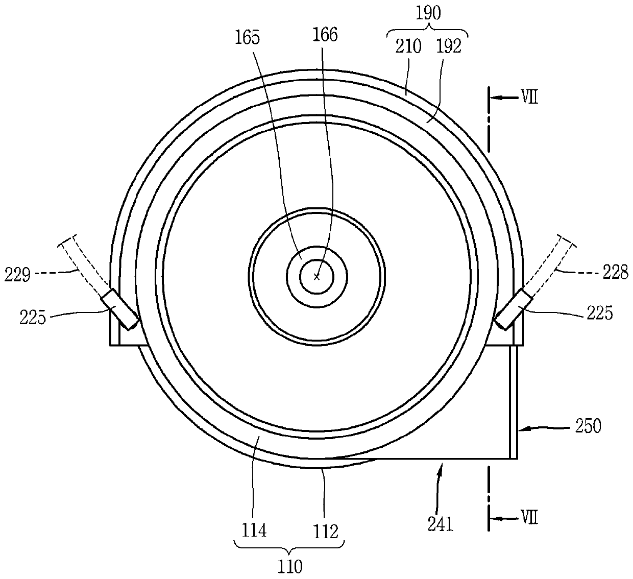
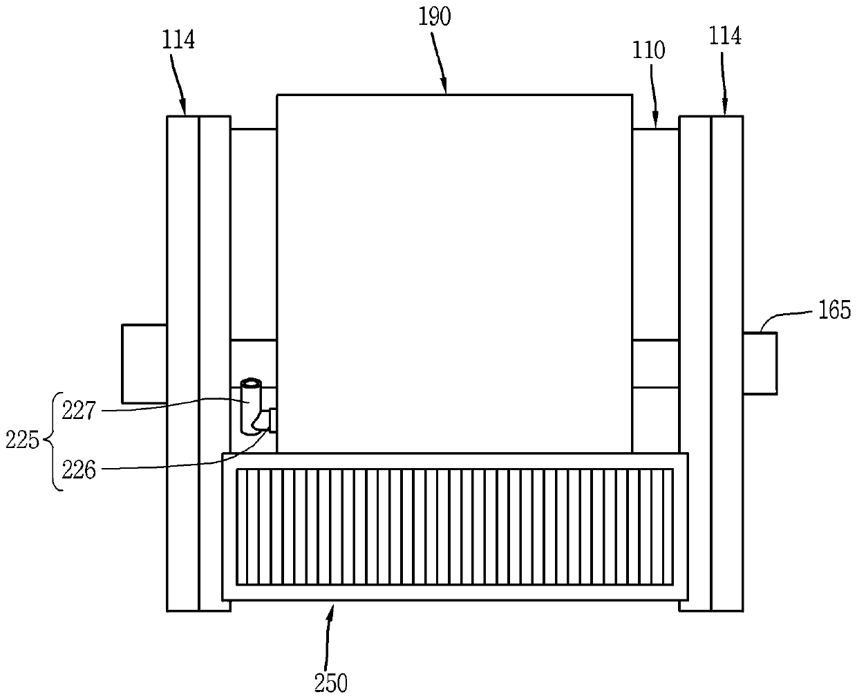
[0093] Such as Figure 1 to Figure 5 As shown, a motor according to an embodiment of the present invention includes: a housing 110 in which an accommod...


PUM


Abstract

An electric motor and method of manufacturing the electric motor are disclosed. The motor includes: a housing in which an accommodation space is formed; a stator accommodated in the housing; a rotor performing relative movement with respect to the stator; and a cooling path portion forming a cooling channel on an outer surface of the housing. A path of fluid, wherein the cooling path portion includes: an outer rib protruding toward an outer surface of the housing and extending in a circumferential direction to form an accommodation space for the cooling fluid therein; an inner rib in the the inner side of the external rib protrudes from the outer surface of the housing, extends in the axial direction and is spaced apart from each other in the circumferential direction to form a path of the cooling fluid; and a cooling path cover is provided in the radial direction of the housing to block the The exterior of the outer ribs and the inner ribs thus together with the outer ribs and the inner ribs form a path for the cooling fluid. In this case, the heat exchange area of ​​the cooling fluid can be increased to improve the cooling performance.

Description

technical field [0001] The invention relates to an electric motor and a manufacturing method thereof, in particular to an electric motor with improved power density through enhanced cooling and a manufacturing method thereof. Background technique [0002] As we all know, an electric motor is a device that converts electrical energy into kinetic energy by utilizing the strength of a current-carrying conductor received in a magnetic field. [0003] According to the type of power supply, electric motors are classified into DC motors and AC motors. [0004] Generally, an electric motor includes a stator and a rotor configured to allow relative movement with respect to the stator. [0005] The rotor is configured for rotational or linear reciprocation relative to the stator. [0006] An electric motor includes a housing in which a stator and a rotor can be accommodated. [0007] When the motor is driven, the temperature of the motor rises due to the heating action of the stato...

Claims


Application Information

Patent Timeline
Patent Type & Authority Patents(China)
IPC IPC(8): H02K5/20H02K9/19H02K9/02
CPCH02K9/02H02K5/203H02K9/225
Inventor 郑楠勋
Owner LG MAGNA E POWERTRAIN CO LTD
Why Eureka
Try Eureka