Automatic weighing feeder for feeding trials that can be fed at regular intervals
What is Al technical title?
Al technical title is built by PatSnap Al team. It summarizes the technical point description of the patent document.
An automatic weighing and feeder technology, applied in animal feeding devices, instruments, applications, etc., can solve the problems of troublesome animals' food intake, large data errors, troubles, etc., and achieve accurate record collection, convenient collection, and prevent slippage. Effect
Active Publication Date: 2020-03-31
山东科锐智能科技有限公司
View PDF5 Cites 0 Cited by
Summary
Abstract
Description
Claims
Application Information
AI Technical Summary
This helps you quickly interpret patents by identifying the three key elements:
Problems solved by technology
Method used
Benefits of technology
Problems solved by technology
When doing a feeding test, it is necessary to weigh how much feed is fed, how much feed the animal has eaten, and how much feed is left. In practice, it is very troublesome to manually weigh and record the weight of the feed during feeding.
Moreover, it will be more troublesome to observe and record the food intake of animals at regular and fixed points, and the data error will be larger
[0003] Furthermore, when regular feeding is required (that is, feeding at different time points in a day), the feeding box can only be put into the feeding box manually according to the feeding time, and the feeding box is taken away manually after the feeding is completed, which is very difficult. trouble
[0004] At present, there is no metering device dedicated to animal feeding experiments. Therefore, designing a device that can automatically measure experimental data and feed regularly will greatly save labor, and the data will be more accurate and the records will not be wrong.
Method used
Image
Click on the blue label to locate the original text in one second.
Reading with bidirectional positioning of images and text.
Examples
Embodiment Construction
[0037] Attached below Figure 1-11 The specific embodiment of the present invention is described in detail:
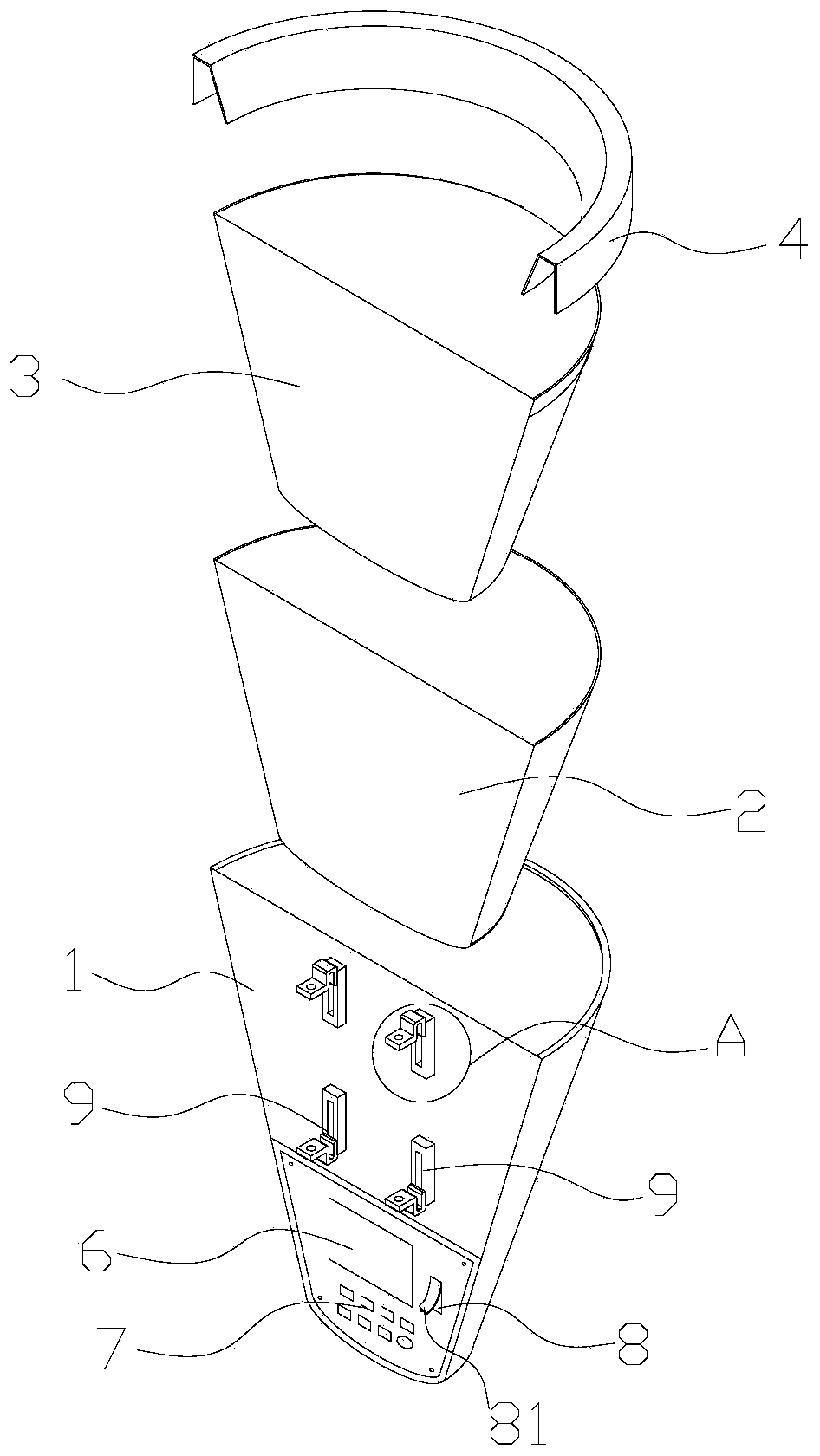
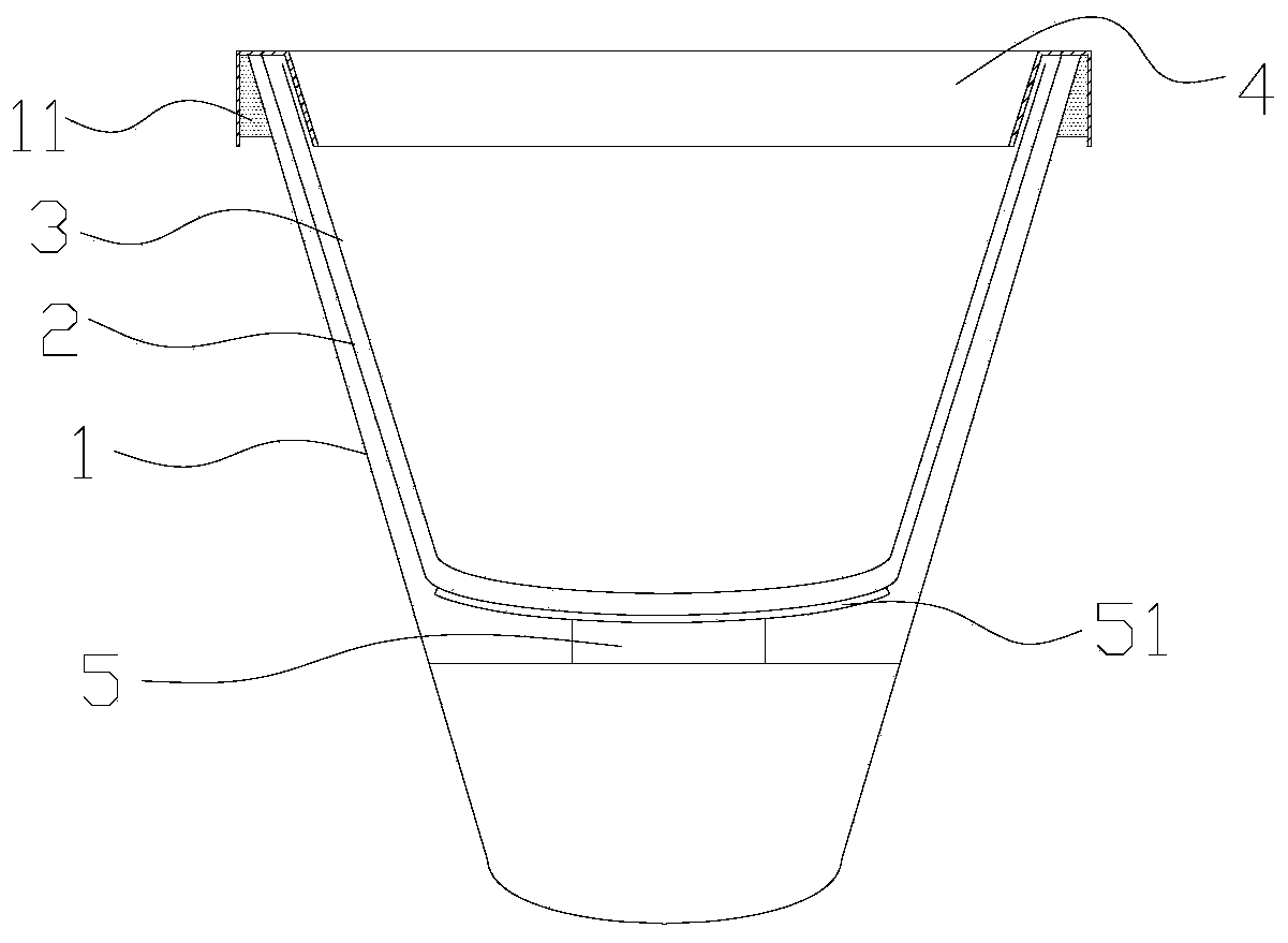
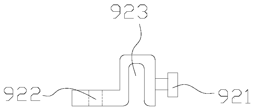
[0038] The present invention includes an outer box body 1 , a material tank 2 and an inner lining tank 3 nested sequentially from outside to inside, and a protective cover 4 covering the upper ends of the outer box body 1 , material tank 2 and inner lining tank 3 . The protective cover 4 is semi-arc-shaped, and the rear end is not closed. A semicircular cover 12 is arranged on the upper end of the outer box body 1 , and a rotating shaft 13 and a stepping motor 14 are arranged on the rear upper end of the outer box body 1 , and the rotating shaft 13 is located in the sleeve 15 . The cover 12 is fixedly connected to the rotating shaft 13 through a connecting rod. Specifically, an arc-shaped opening is provided on the circumference of the sleeve 15, and the two ends of the connecting rod are respectively connected to the rotating shaft 13 and the covering body 12 after p...
PUM
Abstract
The invention provides a timed-feeding automatic weighing feeder for feeding tests. The timed-feeding automatic weighing feeder includes an outer box body, a chute and a liner groove which are sequentially arranged in a sleeving mode from outside to inside, as well as a protective cover. The bottom of the outer box body is provided with an electronic scale, a clock chip and a memory card. The backof the outer box body is provided with a fixing device. A keyboard includes a power switch key, a start key, an end key, a view button, a date key, a timing key and an up and down adjustment button.The automatic weighing feeder further includes an automatic timed weighing unit and an automatic data storage unit. The upper end of the outer box body is provided with a cover body. A rotating shaftand a stepping motor are disposed at the upper end of the rear side of the outer box body. The rotating shaft is located in a sleeve. The timed-feeding automatic weighing feeder can conveniently and automatically weigh the amount of feed, timed weighing and timed feeding can be performed, and timed feeding with an intuitive data package is performed.
Description
technical field [0001] The invention relates to an automatic weighing feeder for feeding experiments that can be fed at regular intervals. Background technique [0002] In the breeding industry, such as mink, fox, pig, cattle, sheep, dog, deer, rabbit and other livestock breeding, as well as chickens, ducks, geese, pigeons, ostriches and other poultry, it is used to test feed when frequent feeding tests are required. The nutrient function, digestion and absorption status, observation of animal food intake in different periods, etc. When doing feeding experiments, it is necessary to weigh the amount of feed, how much feed the animals have eaten, and how much feed is left. In practice, it is very troublesome to manually weigh and record the weight of the feed during feeding. Moreover, it will be more troublesome to observe and record the food intake of animals at regular and fixed points, and the data error will be larger. [0003] Furthermore, when regular feeding is requir...
Claims
Application Information
Patent Timeline
Application Date:The date an application was filed.
Publication Date:The date a patent or application was officially published.
First Publication Date:The earliest publication date of a patent with the same application number.
Issue Date:Publication date of the patent grant document.
PCT Entry Date:The Entry date of PCT National Phase.
Estimated Expiry Date:The statutory expiry date of a patent right according to the Patent Law, and it is the longest term of protection that the patent right can achieve without the termination of the patent right due to other reasons(Term extension factor has been taken into account ).
Invalid Date:Actual expiry date is based on effective date or publication date of legal transaction data of invalid patent.