Hydraulic self-heating sucker-type water cup

A hot straw type, straw technology, applied in drinking vessels, engine components, machines/engines, etc., to achieve the effect of good development space, novel design, and wide application

Pending Publication Date: 2018-04-20
NORTH CHINA UNIV OF WATER RESOURCES & ELECTRIC POWER
View PDF6 Cites 3 Cited by
  • Summary
  • Abstract
  • Description
  • Claims
  • Application Information

AI Technical Summary

Problems solved by technology

[0003] In view of the current situation that most of the existing water cups must be energized to generate heat, and some passive heati

Method used


Image

  • Hydraulic self-heating sucker-type water cup
  • Hydraulic self-heating sucker-type water cup
  • Hydraulic self-heating sucker-type water cup

Examples


Example Embodiment

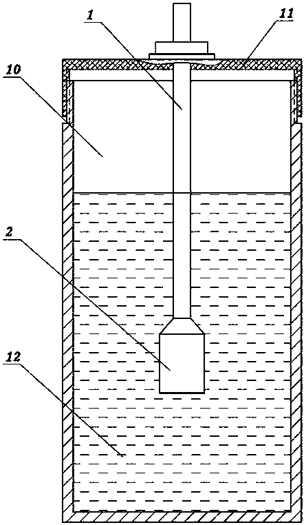
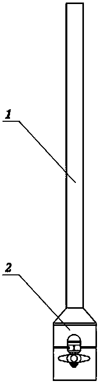
[0022] Example 1: The first hydraulic self-heating straw type water cup, such as figure 1 As shown, necessary components such as the cup body 10, the cup lid, and the straw are included. See figure 2 As shown, the straw includes a straw body 1 on the upper side and a straw heating section 2 on the lower side. The upper end of the straw body 1 leads out of the cup 10 and the straw heating section 2 is located at the bottom of the cup 10.

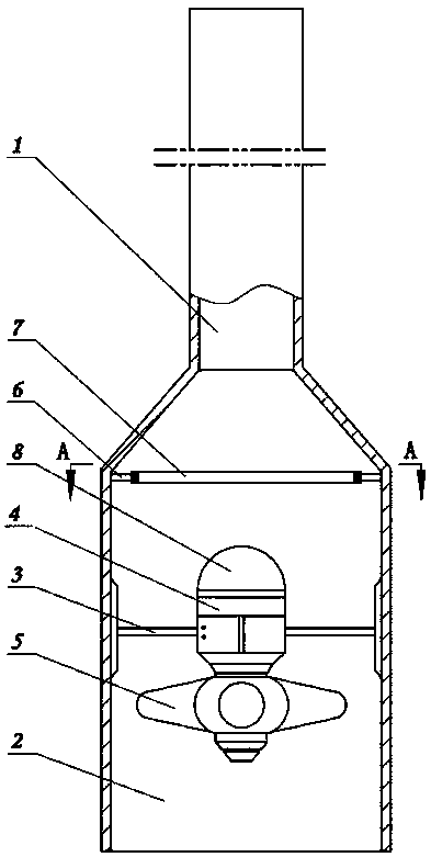
[0023] Such as image 3 As shown, the middle part of the heating inner wall of the straw is fixed with a reversible hydro-generator 4 through a bracket. The shaft of the reversible hydro-generator 4 coincides with the shaft of the heating section 2 of the straw. The turbine blades are installed on the shaft. The resistance wire 7 is fixed on the upper side of the heating section 2 of the straw. The power output end of the reversible water turbine generator 4 is connected to both ends of the resistance wire 7.

[0024] The resistance wire 7 used ...

Example Embodiment

[0030] Example 2: On the basis of Example 1, see Figure 4 , The straw body 1 and the straw heating section 2 have a sealed butt joint structure, and the two parts are processed separately and assembled together.

[0031] In addition, see Image 6 As shown, the resistance wire 7 used in this embodiment is a spiral disc-shaped structure, which is connected to the middle of the straw heating section 2 respectively. Conducive to full contact with water flow to achieve heat exchange.

Example Embodiment

[0032] Embodiment 3: On the basis of embodiment 1 or embodiment 2, a connecting seat 13 is provided on the upper side of the cup lid and located outside the straw body 1, and a connecting seat 13 is installed on the lid that can be flipped and buckled. The upper secondary cover can seal the port of the straw body 1.

[0033] For specific structure, see Figure 7 As shown, the secondary cover is a rotating secondary cover 16 whose two sides are respectively hinged on both sides of the connecting seat 13 by pins 14. After the rotating secondary cover 16 is turned over, the upper port of the straw body 1 can be secondary covered. A fixed arc-shaped shell 15 is sleeved on the outer side of the rotating auxiliary cover 16.


PUM


Abstract

The invention discloses a hydraulic self-heating sucker-type water cup. The cup comprises a cup body, a cup cover and a sucker, the upper end of a main sucker body extends to the outer side of the cupbody, and a reversible water wheel power generator is fixed to the middle of the heating inner wall of the sucker through a support; the axis of a rotation shaft of the reversible water wheel power generator coincides with that of a heating segment of the sucker, and water turbine blades are arranged on the rotation shaft; a resistance wire is fixed to the upper side of the heating segment of thesucker, and a power output end of the reversible water wheel power generator is connected with the two ends of the resistance wire. According to the hydraulic self-heating sucker-type water cup, thesucker has a heating function, an adopted water turbine is a mini-type water turbine, the amount of water which is conveyed by the sucker is low, and the water flow in the sucker is easily heated. Thehydraulic self-heating sucker-type water cup is novel in design, simple in principle and easy to operate, the problem can be well solved that a user wants to drink hot water anytime in winter, and the cup is suitable for a large number of people and has good development space.

Description

Technical field [0001] The invention relates to an improvement technology for drinking cups in the field of daily necessities, in particular to a drinking cup that utilizes hydroelectric power generation and can be used for survival in the wild, cold water heating and hot water insulation in daily life. Background technique [0002] Many people at home like to drink water from a cup or make a drink, but in many cases the liquid in the cup cannot be consumed before the water body becomes warm. There are many disposable plastic straws and straws made of other materials on the market, but these ordinary straws are all disposable products and have no other function besides sucking liquid. Summary of the invention [0003] In view of the current situation that most of the existing water cups must be energized and used to generate heat, and some passive hot water heaters must be driven by external force to generate heat, the present invention provides a hydraulic self-heating straw type...

Claims


Application Information

Patent Timeline
IPC IPC(8): A47G19/22A47G21/18A45F3/16F03B13/00
CPCA45F3/16A47G19/2288A47G21/18F03B13/00
Inventor 王婧丁泽霖柴启辉姜珊程哲兰马寿勋何思平李光亚
Owner NORTH CHINA UNIV OF WATER RESOURCES & ELECTRIC POWER
Why Eureka
Try Eureka