Ultrasonic probe calibration method and calibration device based on electromagnetic positioning technology

An ultrasonic probe and electromagnetic positioning technology, which is applied in the directions of ultrasonic/sonic/infrasonic diagnosis, ultrasonic/sonic/infrasonic image/data processing, and acoustic diagnosis, etc. Problems such as wrong numbering, etc., to achieve the effect of exquisite device design, accurate measurement, and easy identification

Pending Publication Date: 2018-04-20
GUANGZHOU LIAN MED TECH CO LTD
View PDF3 Cites 7 Cited by
  • Summary
  • Abstract
  • Description
  • Claims
  • Application Information

AI Technical Summary

Problems solved by technology

Secondly, manually selecting the coordinates of the bright spots on the ultrasound image is subjective and will introduce random errors
Thirdly, in order to obtain better calibration accuracy, it is often necessary to obtain dozens or even hundreds of N-shaped target points on multiple frames of images. Manual operation takes a long time, which also increases the probability of numbering errors

Method used


Image

  • Ultrasonic probe calibration method and calibration device based on electromagnetic positioning technology
  • Ultrasonic probe calibration method and calibration device based on electromagnetic positioning technology
  • Ultrasonic probe calibration method and calibration device based on electromagnetic positioning technology

Examples


Embodiment 1

[0065] The present invention provides an ultrasonic probe calibration method based on electromagnetic positioning technology, such as Figure 9 shown, including the following steps:

[0066] S1. Ultrasonic image acquisition. Ultrasonic image acquisition is carried out through the integrated experimental platform of electromagnetic positioning and B-ultrasound equipment. The ultrasonic image acquisition method is realized by pulling and collecting the ultrasonic probe fixed on the ultrasonic probe fixed bracket from left to right at equal intervals, and each acquisition interval is 0.5cm, a total of 45 effective ultrasound images were collected. During the collection, the ultrasound probe was immersed in the water surface, the scanning plane was perpendicular to the N-line model, and the marker points were imaged throughout the entire ultrasound imaging area.

[0067] S2. Ultrasound image preprocessing. 45 ultrasound images, 7 layers of double N lines, 35 feature markers in e...

Embodiment 2

[0084] On the basis of the ultrasonic probe calibration method based on the electromagnetic positioning technology disclosed in the first embodiment, this embodiment provides an ultrasonic probe calibration device based on the electromagnetic positioning technology.

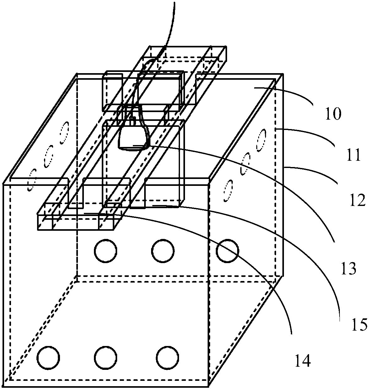
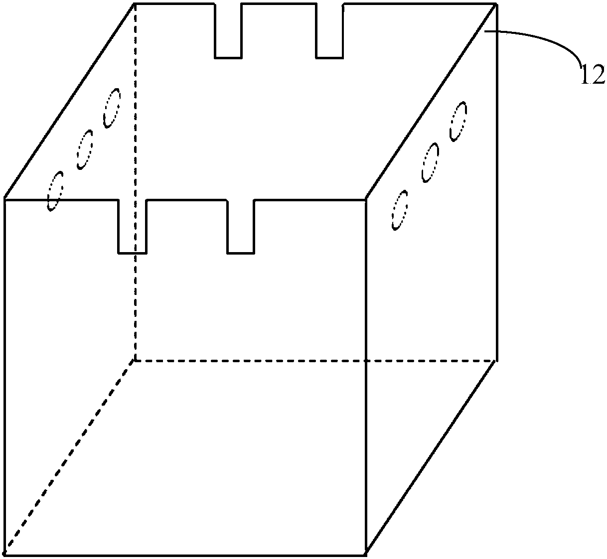
[0085] Such as figure 1 As shown in Figure 5, the present invention provides an ultrasonic probe calibration device based on electromagnetic positioning technology, which is an integrated device 10 for collecting ultrasonic images, wherein the inner water tank 11 is placed in the outer water tank, and the upper concave The position of the groove coincides with the fixing holes on the left and right sides, and the ultrasonic probe fixing bracket is placed on the groove of the water tank.

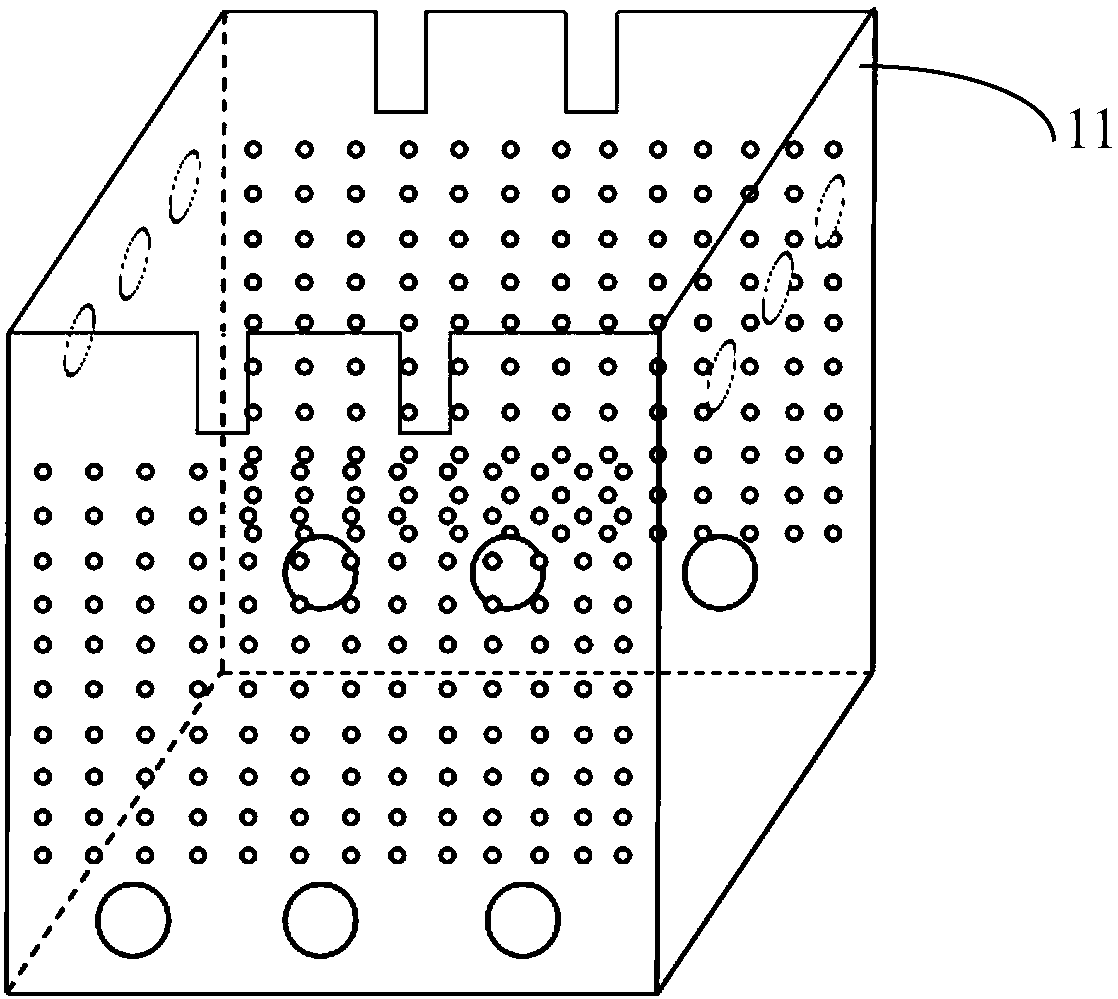
[0086] 20*24 small holes with a diameter of 1.5mm are drilled on the front and rear opposite sides of the inner tank 11, which are used to build a 7-layer double N line model. There are six positioning holes with a diameter of ...


PUM


Abstract

The invention discloses an ultrasonic probe calibration method and calibration device based on an electromagnetic positioning technology. The ultrasonic probe calibration method includes the followingsteps: 1) performing ultrasonic image acquisition, 2) performing ultrasonic image preprocessing, and adopting an adaptive threshold method to automatically identify and sort ultrasonic image markingpoints; and 3) solving a calibration matrix, namely a coordinate conversion matrix between an ultrasonic image coordinate system and an electromagnetic positioning sensor coordinate system. The ultrasonic probe calibration device includes an electromagnetic positioning system, a B-ultrasonic device, an internal cuboid water tank, an external cuboid water tank, ultrasonic sound-absorbing cotton, aseven-layer double N-type nylon thread and an ultrasonic probe fixing bracket. In the calibration method, the electromagnetic positioning technology and a B-ultrasonic image are combined, the calculation process is fully automatic, and the method can adapt to different types of ultrasonic probes. The device is simple and convenient and is applied to the field of obstetrical delivery monitoring, and accurate measurement and 3D visualization of the position of the fetal head and the orientation of the fetal head can be achieved.

Description

technical field [0001] The invention relates to the technical field of fusion of medical ultrasonic imaging, electromagnetic positioning, and image processing technology, in particular to an ultrasonic probe calibration method and calibration device based on electromagnetic positioning technology. Background technique [0002] Medical ultrasound imaging technology has the advantages of low price, no ionizing radiation, real-time imaging, and percutaneous non-invasiveness. It is widely used in the field of obstetric and delivery monitoring, and can assist doctors in the diagnosis of fetal head position and orientation. Traditional two-dimensional ultrasound technology can only provide two-dimensional images of fetal cross-sections. Clinicians mainly rely on experience to reconstruct the three-dimensional structure of the fetal head in their brains. This process is not only time-consuming, inefficient, but also subjective. With the development of computer technology, three-dim...

Claims


Application Information

Patent Timeline
Patent Type & Authority Applications(China)
IPC IPC(8): A61B8/00
CPCA61B8/52A61B8/5215
Inventor 陆尧胜刘高超覃树城
Owner GUANGZHOU LIAN MED TECH CO LTD
Why Eureka
Try Eureka