
Corrugated pipe cutting machining device

A cutting and corrugated pipe technology, applied in metal processing and other directions, can solve the problems that the efficiency of corrugated pipes needs to be improved, the simultaneous cutting of multiple corrugated pipes cannot be realized, and the cutting efficiency is low.

Active Publication Date: 2018-04-20
SHANDONG WANSHIDA SPECIAL PURPOSE VEHICLE MFG
View PDF5 Cites 3 Cited by
  • Summary
  • Abstract
  • Description
  • Claims
  • Application Information

AI Technical Summary

Problems solved by technology

However, the cutter on the corrugated pipe cutting device can only cut one corrugated pipe at a time, but cannot cut multiple corrugated pipes at the same time, and the cutting efficiency is low, so the efficiency of corrugated pipe cutting needs to be improved

Method used


Image

  • Corrugated pipe cutting machining device

Examples


Embodiment Construction

[0014] Further detailed explanation through specific implementation mode below:

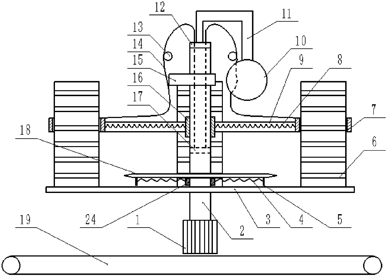
[0015] The reference signs in the drawings of the description include: motor 1, rotating shaft 2, supporting plate 3, second spring 4, push plate 5, bellows 6, fixed cylinder 7, first spring 8, telescopic rod 9, air bag 10, Air pipe 11, sealing cover 12, pulley 13, steel wire 14, cam 15, first bearing 16, piston 17, cutter 18, conveyor belt 19, second bearing 24.

[0016] The embodiment is basically as attached figure 1 Shown: a bellows cutting processing device, including a motor 1, a rotating shaft 2 and a circular cutter 18, the bottom of the rotating shaft 2 is connected to the motor 1, the rotating shaft 2 is connected to the cutter 18, and the rotating shaft 2 is connected to the The first bearing 16 located above the tool 18 and the second bearing 24 located below the tool 18 are connected in rotation, and two telescopic rods 9 are welded on the first bearing 16, and the telescopic rods 9...


PUM


Abstract

The invention relates to a corrugated pipe cutting machining device. The corrugated pipe cutting machining device comprises a motor, a rotary shaft and a round cutter; the bottom end of the rotary shaft is connected with the motor, and the upper end of the rotary shaft is connected with the cutter; a first shaft sleeve located above the cutter and a second shaft sleeve located below the cutter arerotationally connected to the rotary shaft; a plurality of telescopic rods are connected to the first shaft sleeve, the ends, away from the first shaft sleeve, of the telescopic rods are all providedwith fixed barrels, and first springs are connected with the fixed barrels and the first shaft sleeve; second springs are connected to the second shaft sleeve; the rotary shaft is internally providedwith a cavity, and a piston is movably connected into the cavity; a sealing cover is rotationally connected to the top end of the rotary shaft and provided with an opening; the rotary shaft is fixedly connected with a cam and a supporting plate located under the second shaft sleeve, one side of the cam is provided with an air bag, and the air bag and the sealing cover communicate with an air pipe; the outer side of the rotary shaft is rotationally connected with pulleys; and stay cords are connected with the piston and the fixed barrels and penetrate through the opening to be arranged on thepulleys. Through the corrugated pipe cutting machining device, a plurality of corrugated pipes can be cut at the same time.

Description

technical field [0001] The invention relates to the technical field of bellows processing, in particular to a bellows cutting and processing device. Background technique [0002] At present, there is a great demand for corrugated pipes in the market, and customers need corrugated pipes of different specifications, so a corrugated pipe cutting device is needed for processing and cutting, and the longer corrugated pipes are cut into shorter corrugated pipes to obtain different specifications of corrugated pipes. Bellows. [0003] Now the corrugated pipe cutting device is equipped with a cutter, and the corrugated pipe is cut by the high-speed rotation of the cutter. However, the cutter on the bellows cutting device can only cut one bellows at a time, but cannot cut multiple bellows at the same time, and the cutting efficiency is low, so the efficiency of bellows cutting needs to be improved. Contents of the invention [0004] The object of the present invention is to provi...

Claims


Application Information

Patent Timeline
Patent Type & Authority Applications(China)
IPC IPC(8): B26D1/147B26D5/38B26D7/01
CPCB26D1/147B26D5/38B26D7/01B26D2007/013
Inventor 陈昌华
Owner SHANDONG WANSHIDA SPECIAL PURPOSE VEHICLE MFG
Learn More