Transmission method and transmission structure for circulating conveying trays

A transmission structure and cyclic conveying technology, applied in conveyors, mechanical conveyors, transportation and packaging, etc., can solve the problems of low transmission precision, complex transmission structure and high cost of construction, and achieve high transmission precision, simple transmission structure, Good load-bearing effect

Active Publication Date: 2018-04-20
LILING LVYUAN COMML & TRADING CO LTD
View PDF10 Cites 0 Cited by
  • Summary
  • Abstract
  • Description
  • Claims
  • Application Information

AI Technical Summary

Problems solved by technology

[0007] The circulating conveying tray in the existing material intelligent distribution system has disadvantages such as poor load-bearing capacity, low transmission accuracy, complex transmission structure, and high cost.

Method used


Image

  • Transmission method and transmission structure for circulating conveying trays
  • Transmission method and transmission structure for circulating conveying trays
  • Transmission method and transmission structure for circulating conveying trays

Examples


Embodiment 1

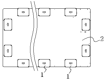
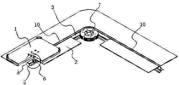
[0032]Embodiment 1: as figure 2 and Figure 5 As shown, a transmission method for circularly conveying pallets is to connect multiple pallets 1 with the timing belt 3 of the synchronous belt transmission mechanism. Driven by the synchronous belt transmission mechanism, multiple pallets 1 can move along the Circular rotation, a plurality of support wheels 4 are arranged on the bottom of each tray 1, and the plurality of support wheels 4 are in contact with the working platform 2 to carry out load bearing on the tray 1 and the distribution box frame placed on the tray 1; A guide rail mechanism 5 is set on the working platform 2, and a guide wheel mechanism 6 is arranged on the bottom of each tray 1, and the precise transmission of the tray 1 is realized through the contact and cooperation between the guide rail mechanism 5 and the guide wheel mechanism 6. This embodiment utilizes a plurality of supporting wheels to roll and support on the working platform for load-bearing duri...

Embodiment 2

[0039] Embodiment 2: as Figure 8 and Figure 9 As shown, compared with Embodiment 1, the difference is that a plurality of support wheels 4 in this embodiment are in contact with the top of the work platform 1, the guide rail mechanism 5 is arranged on the top of the work platform 1, and the guide wheel mechanism 6 Cooperate with the guide rail mechanism 5 on the top of the working platform.

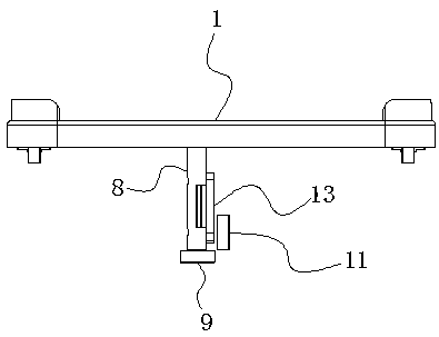
[0040] The guide rail mechanism is 5 convex lines arranged on the working platform, and the convex lines include convex line 1 to convex line 4 (only convex line 1 513 and convex line 2 514 are drawn in the figure), and convex line 1 to convex line 4 are in the form of The rectangular shape is distributed on the working platform 2 and the ends of the adjacent two raised strips are disconnected (that is, at the four corners of the working platform, the two raised strips are disconnected instead of continuous); the guide wheel mechanism 6 includes a horizontal guide wheel 15 connected t...


PUM


Abstract

The invention discloses a transmission method and transmission structure for circulating conveying trays. According to the transmission method, the multiple trays are connected with a synchronous beltof a synchronous belt transmission mechanism, under driving of the synchronous belt transmission mechanism, the multiple trays can rotate along a working platform circularly, multiple supporting wheels are arranged on the bottom of each tray, by means of contact cooperation of the multiple supporting wheels and the working platform, the trays and delivery boxes placed on the trays are supported,a guide rail mechanism is arranged on the working platform, a guide wheel mechanism is arranged on the bottom of each tray, and by means of contact cooperation of the guide rail mechanism and the guide wheel mechanisms, precise transmission of the trays is achieved. According to the transmission method and the transmission structure, the supporting performance is good, the transmission precision is high, the transmission structure is simple, and the manufacturing cost is reduced.

Description

technical field [0001] The invention relates to a transmission method and a transmission structure of components in an intelligent material distribution system, in particular to a transmission method and a transmission structure of a circular conveying tray. Background technique [0002] At present, with the continuous development of social economy and the arrival of Internet technology, people's demand for various materials has undergone fundamental changes. Many of them are already traded through the Internet and then distributed through logistics companies. For example, in the past, restaurants bought food through their own buyers to go to the vegetable market to purchase, but now many order directly through the Internet or video, and then the deliveryman delivers the goods to the door; Ordering food by phone, but now more and more people order food online, and then deliver it to the door; because this kind of online ordering is fast, convenient, does not need to go out, ...

Claims


Application Information

Patent Timeline
IPC IPC(8): B65G35/00
CPCB65G35/00
Inventor 欧阳天勇
Owner LILING LVYUAN COMML & TRADING CO LTD
Why Eureka
Try Eureka