
Melt spinning machine

A spinning machine and spinning technology, used in melt spinning, filament generation, textiles and papermaking, etc., can solve the problems of complex operation, single state, low efficiency, etc., and achieve the effect of enriching effective data and diversifying types.

Pending Publication Date: 2018-04-20
苏州金纬化纤装备有限公司
View PDF10 Cites 1 Cited by
  • Summary
  • Abstract
  • Description
  • Claims
  • Application Information

AI Technical Summary

Problems solved by technology

[0002] At present, spinning is diversified, there are many types of resin materials that can be processed, and the requirements for fiber tow in post-processing are various. The main purpose of the existing melt spinning machine that can be used in experiments is to verify the spinning performance of resin materials and seek Process parameters provide effective data for the large-scale production of melt spinning machines; however, the existing spinning machines used in experiments have poor versatility and can only process a small amount of several materials or spun fiber tows that have The state is single, and the user needs to prepare multiple sets of different equipment to spin various types of fiber tow, which is complicated and inefficient
[0003] The Chinese patent whose publication number is CN20362772U discloses "a kind of micro-melt spinning machine", which is mainly used for experiments. system and combined support, the spinning system is suspended and fixed by the combined support, the pressurization system is placed above the spinning system, the feeding system is placed on the side of the spinning system, and the cooling system is placed between the spinning system and the stretching system. The combined support is fixed, although continuous filaments can be spun and the amount of materials used is less, but the spun fiber tows are limited to filament tows, and conventional synthetic fibers such as polyester, nylon, and polypropylene cannot be spun. Resin fibers still have the problem of low spinning versatility

Method used


Image

  • Melt spinning machine

Examples


Embodiment Construction

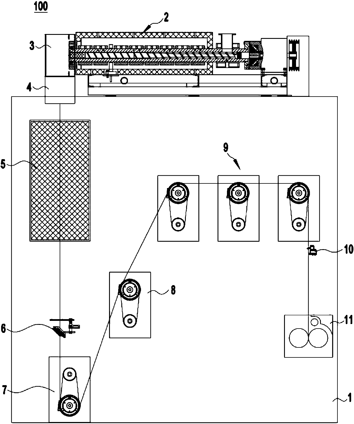
[0017] In order to describe the technical content, structural features, achieved goals and effects of the invention in detail, the following will be described in detail in conjunction with the embodiments and accompanying drawings. Among them, the "up", "down", "left", and "right" mentioned in this embodiment refer to the attached figure 1 up, down, left, and right directions shown in .

[0018] as attached figure 1 As shown, it is a schematic structural diagram of a melt spinning machine. The melt spinning machine 100 includes a frame 1, a melt extrusion mechanism 2, a metering mechanism 3, a spinning mechanism 4, a cooling mechanism 5, a wire adjustment mechanism 6, a A guide plate mechanism 7, a second guide plate mechanism 8, a third guide plate mechanism 9, a wire guide mechanism 10 and a winding mechanism 11, wherein the melt extrusion mechanism 2 is a plastic extruder, and the plastic extruder includes The barrel is equipped with an extruding screw rotating inside the...


PUM


Abstract

The invention discloses a melt spinning machine, and belongs to the field of spinning equipment. The technical problem in the prior art that the universality of the melt spinning machine for experiments is not good, the variety of spinning resin fibers is less, and the type is singular is solved. The melt spinning machine comprises a machine frame, a melt extruding mechanism, a measuring mechanism, a spinning mechanism, a cooling mechanism, a silk regulating mechanism, a first guide disc mechanism, a second guide disc mechanism, a third guide disc mechanism, a silk guide mechanism and a rolling mechanism. Each mechanism is installed on the machine frame according to a spinning technology sequence, and the speed difference between the guide disc mechanisms is regulated, so the resin fiberscan form the different types of fiber tows through the first, second and third guide disc mechanisms. Compared with the prior art, the types of the resin fibers spun by the melt spinning machine are diversified, more technological parameters can be obtained while the multiple different types of the fiber tows are spun by the spinning machine, and more abundant effective data is provided for the industrial production.

Description

technical field [0001] The invention relates to the field of spinning equipment, in particular to a melt spinning machine used for experiments. Background technique [0002] At present, spinning is diversified, there are many types of resin materials that can be processed, and the requirements for fiber tow in post-processing are various. The main purpose of the existing melt spinning machine that can be used in experiments is to verify the spinning performance of resin materials and seek Process parameters provide effective data for the large-scale production of melt spinning machines; however, the existing spinning machines used in experiments have poor versatility and can only process a small amount of several materials or spun fiber tows that have The state is single, and the user needs to prepare multiple sets of different equipment to spin various types of fiber tows, which makes the operation complicated and inefficient. [0003] The Chinese patent whose publication ...

Claims


Application Information

Patent Timeline
IPC IPC(8): D01D13/00D01D11/00D01D5/08
CPCD01D5/08D01D11/00D01D13/00
Inventor 何海潮吴镇波吕山
Owner 苏州金纬化纤装备有限公司
Learn More