Frame beam and column connecting joint comprising replaceable energy dissipation part

A technology of beam-to-column connection and frame-beam, which is applied in the direction of building types, buildings, protected buildings/shelters, etc., can solve the problems of dissipating seismic energy, ductility, and limited improvement in energy dissipation capacity, and reduce repair costs , Improve the effect of repair efficiency, high ductility and energy dissipation capacity

Pending Publication Date: 2018-04-20
HEFEI UNIV OF TECH
View PDF8 Cites 13 Cited by
  • Summary
  • Abstract
  • Description
  • Claims
  • Application Information

AI Technical Summary

Problems solved by technology

However, the fully bolted assembly joints in the related art mainly dissipate the seismic energy through the slippage of the contact surface between the bolted components, and the improvement in ductility and energy dissipation capacity is very limited.

Method used


Image

  • Frame beam and column connecting joint comprising replaceable energy dissipation part
  • Frame beam and column connecting joint comprising replaceable energy dissipation part
  • Frame beam and column connecting joint comprising replaceable energy dissipation part

Examples


Embodiment Construction

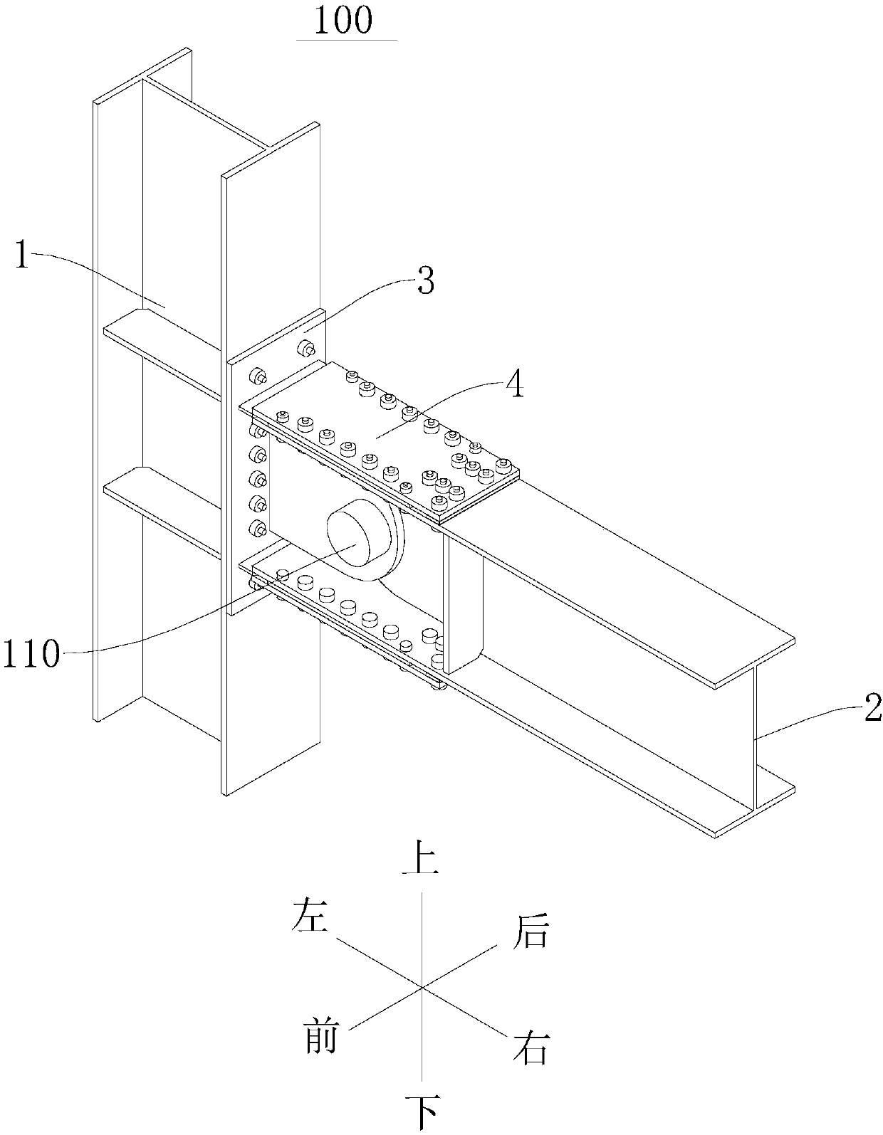
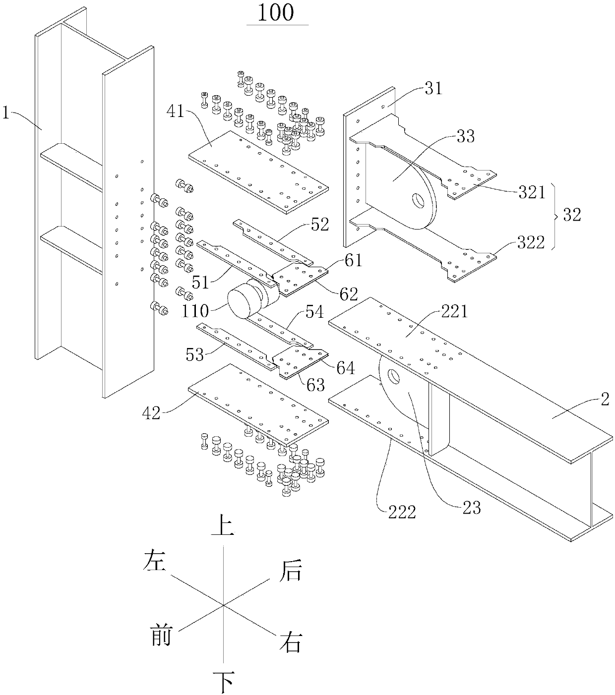
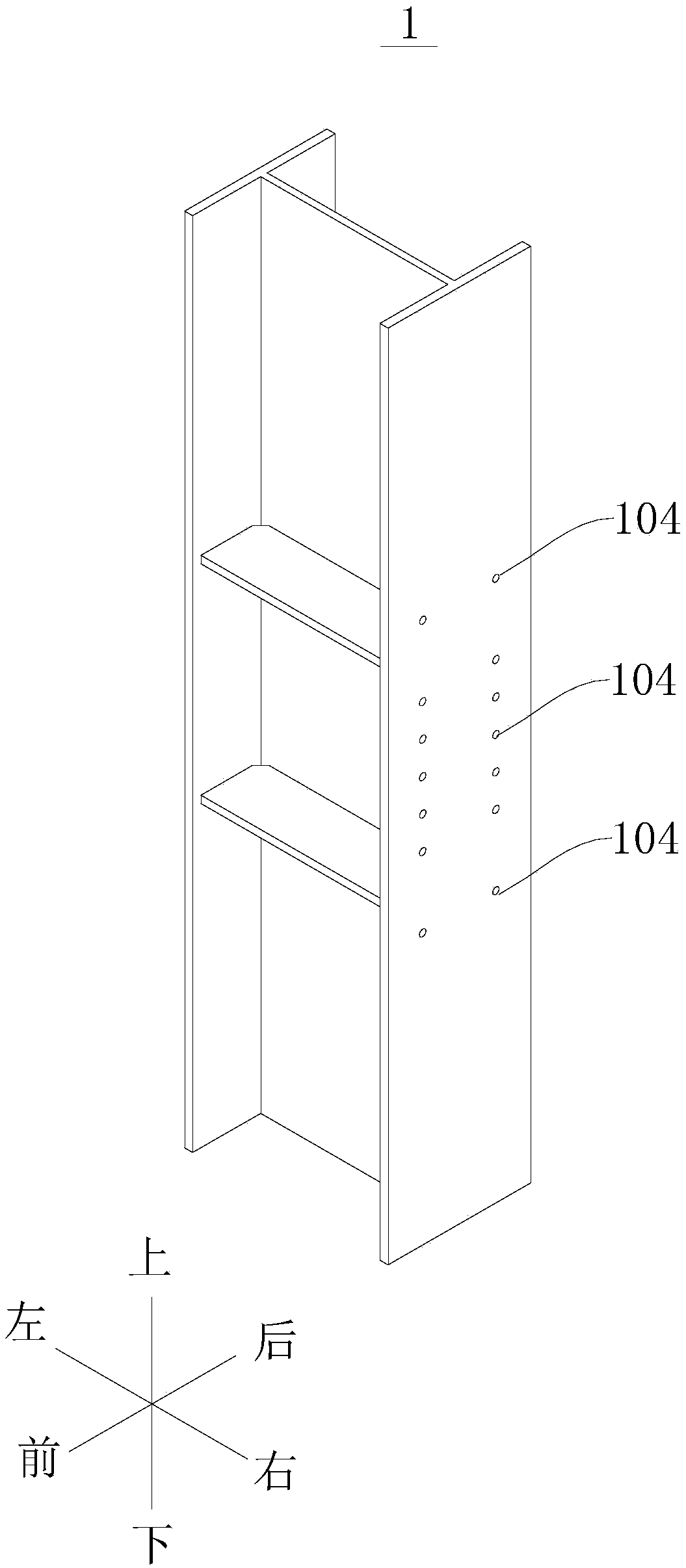
[0042] Embodiments of the present invention are described in detail below, examples of which are shown in the drawings, wherein the same or similar reference numerals designate the same or similar elements or elements having the same or similar functions throughout. The embodiments described below by referring to the figures are exemplary only for explaining the present invention and should not be construed as limiting the present invention.

[0043] In describing the present invention, it is to be understood that the terms "thickness", "upper", "lower", "front", "rear", "left", "right", "vertical", "horizontal", The orientations or positional relationships indicated by "top", "bottom", "inner", "outer", etc. are based on the orientations or positional relationships shown in the drawings, and are only for the convenience of describing the present invention and simplifying the description, rather than indicating or implying References to devices or elements must have a particul...


PUM


Abstract

The invention discloses a frame beam and column connecting joint comprising a replaceable energy dissipation part. The frame beam and column connecting joint comprises a frame column, a frame beam, the energy dissipation part and a restraining plate,wherein the frame beam includes a beam body section, a wing plate and a web plate; the energy dissipation part comprises an energy dissipation plate and a connecting lug plate, the energy dissipation plate includes an energy dissipation section, a column side connecting section and a beam side connecting section, wherein the column side connectingsection and the beam side connecting section are arranged at both ends of the energy dissipation section, the yield forces of the column side connecting section and the beam side connecting section are both greater than that of the energy dissipation section, the column side connecting section is detachably and fixedly connected with the frame column, the beam side connecting section is detachablyand fixedly connected with the frame beam, and the web plate is detachably connected with the connecting lug plate in a hinged mode; the restraining plate and the wing plate are correspondingly and fixedly arranged on both sides of the energy dissipation plate so as to limit sided displacement of the energy dissipation section, and gaps are arranged between the restraining plate and the energy dissipation section as well as between the wing plate and the energy dissipation section. According to the frame beam and column connecting joint, the ductility and energy dissipation capacity are high,the seismic performance is good, and the restoration efficiency is high after an earthquake, and the repairing cost is low.

Description

technical field [0001] The invention relates to the field of civil engineering, in particular to a frame beam-column connection node with replaceable energy-consuming parts. Background technique [0002] Earthquake is one of the major natural disasters in human history, which has brought huge casualties and economic losses to human society. If the post-earthquake repair countermeasures are not considered in the design, it may be difficult to repair or the repair time will be very long, which will seriously affect the emergency and normal use after the disaster. How to design a recoverable functional structure, component or connection node, which can restore its normal function as soon as possible after an earthquake has become one of the important research directions for sustainable development of engineering structure earthquake resistance. [0003] In the Northridge earthquake in 1994 and the Kobe earthquake in 1995, a large number of beam-column rigid joints such as full...

Claims


Application Information

Patent Timeline
Patent Type & Authority Applications(China)
IPC IPC(8): E04B1/19E04H9/02E04B1/58
CPCE04B1/19E04B1/1903E04H9/021E04B2001/1924
Inventor 冯玉龙种迅蒋庆
Owner HEFEI UNIV OF TECH
Why Eureka
Try Eureka