Self-resetting frame-shear wall structure and construction method for strengthening earthquake-damaged frames
A shear wall and self-resetting technology, applied in the direction of wall, earthquake resistance, building components, etc., can solve the problems of structural damage and non-structural component damage, achieve low seismic loss, reduce seismic damage, avoid seismic damage and two effect of secondary loss
- Summary
- Abstract
- Description
- Claims
- Application Information
AI Technical Summary
Problems solved by technology
Method used
Image
Examples
specific Embodiment approach 1
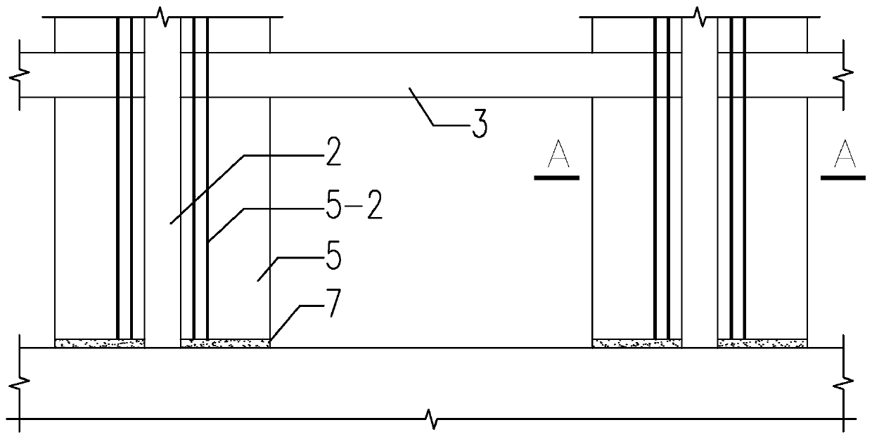
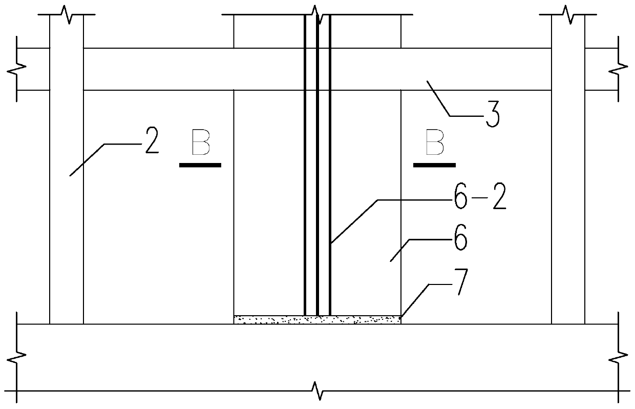
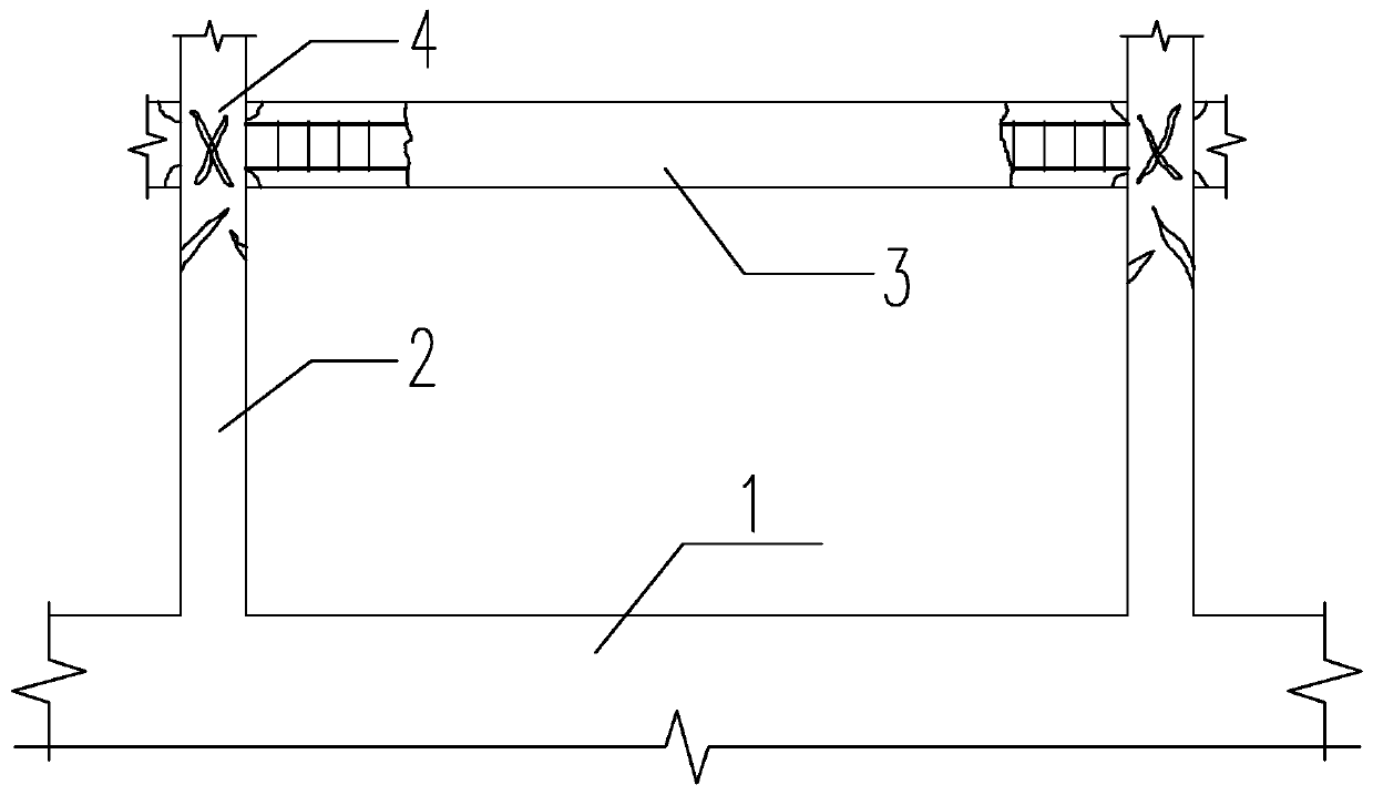
[0046] Specific implementation mode one: combine figure 1 , Figure 3 to Figure 8 and Figure 10 Describe this embodiment, a self-resetting frame-shear wall structure for strengthening the earthquake-damaged frame described in this embodiment includes an earthquake-damaged frame 1, frame columns 2, frame beams 3 and beam-column nodes 4; it also includes multiple Rear shear walls 5 on the column side and fiber cement slurry layer 7, multiple rear shear walls 5 on the column side are arranged symmetrically or on three sides or four sides and installed on the frame column 2, and the rear shear walls 5 on the column side A certain height is reserved at the bottom, and the fiber cement slurry layer 7 is formed by pressure filling within the reserved height range. The reserved height is 25mm-35mm, and the post shear wall 5 is placed on the side of the column on multiple frame column sides within the structural plane range. Arranged as needed, spanning multiple layers in the vertic...
specific Embodiment approach 2
[0049] Specific implementation mode two: combination figure 1 , Figure 7 , Figure 8 and Figure 10 Describe this embodiment, each column-side rear shear wall 5 in this embodiment includes multiple column-side tunnels 5-1, multiple column-side prestressed tendons 5-2, and multiple column-side lower anchors 5-3 , multiple anchors 5-4 on the column side, 5-5 multiple pin key reinforcement bars on the column side, 5-6 vertically distributed reinforcement bars on the column side, 5-7 horizontally distributed reinforcement bars on the column side, and 5 multiple energy-dissipating reinforcement bars on the column side -11; the column side channel 5-1 is vertically arranged parallel to the height direction of the frame column 2, the column side prestressed tendons 5-2 are pierced in the column side channel 5-1, and the lower end of the column side prestressed tendons 5-2 passes through The lower anchor 5-3 on the column side is anchored below the fiber cement slurry layer 7 at t...
specific Embodiment approach 3
[0050] Specific implementation mode three: combination figure 1 , Figure 7 , Figure 8 and Figure 10 To illustrate this embodiment, each column-side rear shear wall 5 of this embodiment also includes column-side tie bars 5-8, column-side edge-constrained longitudinal reinforcements 5-9 and column-side edge-constrained area stirrups 5- 10. The tie bars 5-8 on the column side are arranged at an interval of no more than 600mm in the horizontal direction and the vertical direction, and the double-row reinforcement mesh formed by the vertically distributed steel bars 5-6 on the column side and the horizontally distributed steel bars 5-7 on the column side The bottom of vertically distributed steel bars 5-6 on the column side and the longitudinal bars 5-9 in the restricted area on the edge of the column do not extend into the foundation, and the vertically distributed steel bars 5-6 on the column side and the top of longitudinal bars 5-9 in the restricted area on the edge of the...
PUM
 Abstract
Description
Claims
Application Information
 - R&D
- Intellectual Property
- Life Sciences
- Materials
- Tech Scout
- Unparalleled Data Quality
- Higher Quality Content
- 60% Fewer Hallucinations
Browse by: Latest US Patents, China's latest patents, Technical Efficacy Thesaurus, Application Domain, Technology Topic, Popular Technical Reports.
© 2025 PatSnap. All rights reserved.Legal|Privacy policy|Modern Slavery Act Transparency Statement|Sitemap|About US| Contact US: help@patsnap.com


