Vacuum pump buffer tank

A buffer tank and vacuum pump technology, which is applied in the direction of pumps, pump components, variable capacity pump components, etc., can solve the problems of inability to mix gas, increase the time of gas mixing, and inability to buffer gas multiple times, achieving a good buffer effect

Active Publication Date: 2018-04-20
NANTONG BEIKE VACUUM MACHINERY CO LTD
View PDF6 Cites 0 Cited by
  • Summary
  • Abstract
  • Description
  • Claims
  • Application Information

AI Technical Summary

Problems solved by technology

[0003] The existing technology has the following technical problems: 1. During the process of vacuuming the gas tank, the gas cannot be mixed, which increases the mixing time of the subsequent gas; 2. Only one buffer tank is used to buffer the gas, and the gas cannot be mixed multiple times. Cushioning, the buffering effect is not good

Method used


Image

  • Vacuum pump buffer tank
  • Vacuum pump buffer tank
  • Vacuum pump buffer tank

Examples


Embodiment Construction

[0021] The present invention will be described in further detail below by means of specific embodiments:

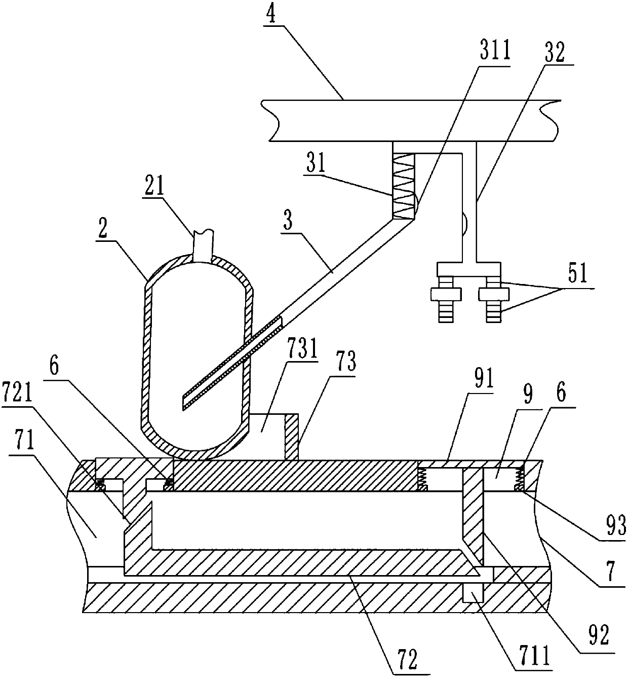
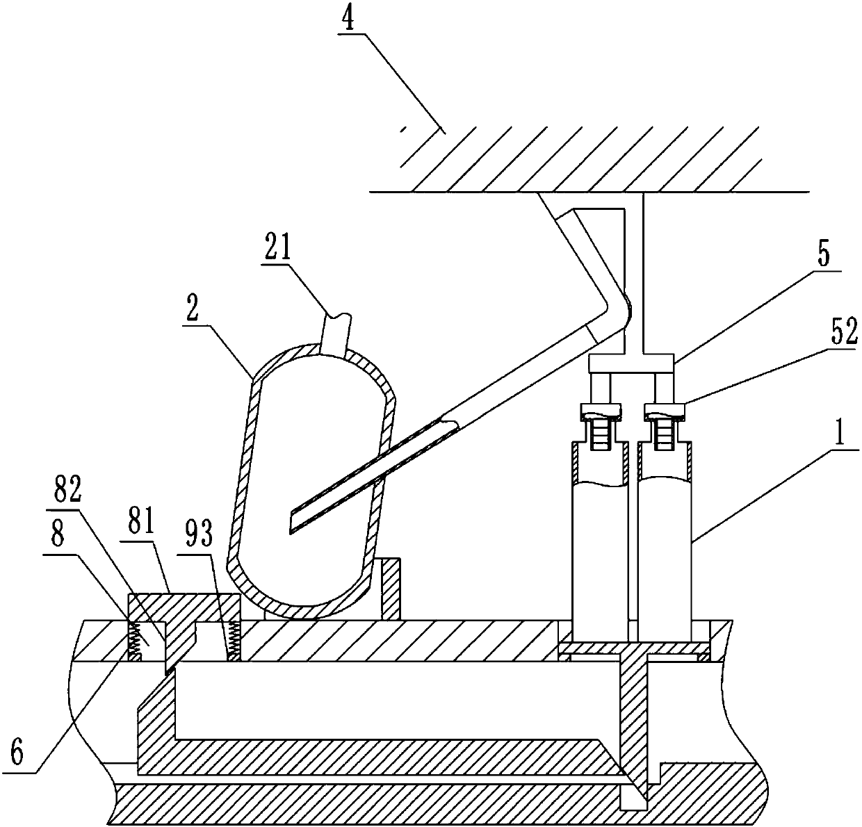
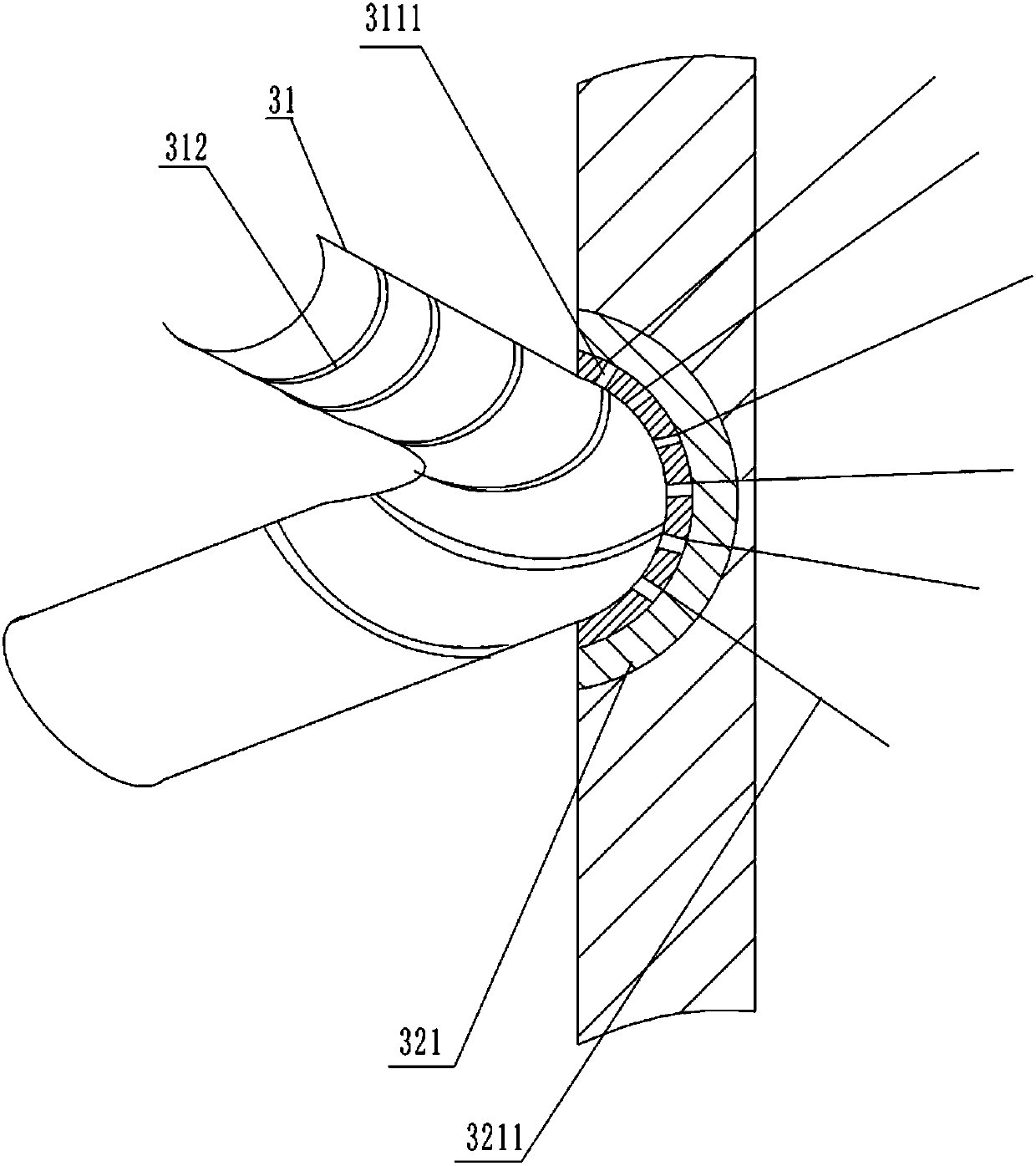
[0022] The reference signs in the drawings of the description include: gas tank 1, buffer tank body 2, air outlet pipe 21, first pipe 3, elastic telescopic tube 31, first magnet 311, through hole 3111, sheet-shaped protrusion 312, third Pipeline 32, second magnet 321, vibrating plate 3211, fixed part 4, suction plate 5, elastic tube 51, chuck 52, return spring 6, placement plate 7, sliding chamber 71, slot 711, sliding rod 72, top Out rod 721, positioning block 73, arc mouth 731, push cavity 8, push block 81, push rod 82, place cavity 9, place block 91, place bar 92, retaining ring 93.

[0023] In order to achieve the above object, the basic scheme of the present invention is as follows:

[0024] like figure 1 , figure 2 and image 3 As shown, a buffer tank for a vacuum pump includes a buffer pipeline and a buffer tank body 2 inclined downward toward the direction of...


PUM


Abstract

The invention relates to the technical field of vacuum pumps, in particular to a vacuum pump buffer tank. The vacuum pump buffer tank comprises buffer pipelines and a buffer tank body which inclines downwards facing gas tanks under the gravity of the gas tanks, the upper portion of the buffer tank body is provided with a gas outlet pipe, the buffer pipelines comprise a first pipeline, a second pipeline and a third pipeline, one end of the first pipeline inclines downwards and stretches into the buffer tank body, the second pipeline is an elastic extension pipe, the side wall of the elastic extension pipe is provided with a first magnet, the other end of the first pipeline is connected with one end of the elastic extension pipe, the other end of the elastic extension pipe is connected withone end of the third pipeline, the upper end of the third pipeline is provided with a fixing portion used for fixing the third pipeline, the side, close to the elastic extension pipe, of the third pipeline is further provided with a second magnet which is in mutual attraction with the first magnet, and the second magnet is further provided with vibrating pieces used for stretching into the third pipeline. By means of the vacuum pump buffer tank, gases can be mixed in the process of vacuuming the gas tanks, and the gases can further be buffered for many times.

Description

technical field [0001] The invention relates to the technical field of vacuum pumps, in particular to a vacuum pump buffer tank. Background technique [0002] The function of the buffer tank is to prevent impurities in the vacuum pipeline from entering the vacuum pump and to protect the safe and stable operation of the vacuum pump. Vacuum pumps are used in various fields, such as the chemical field; in the chemical field, people often mix two gases evenly for experiments. Generally, vacuum pumps are used to pump the gases in two gas tanks, and then put them into a mixing bag for mixing. [0003] The existing technology has the following technical problems: 1. During the process of vacuuming the gas tank, the gas cannot be mixed, which increases the mixing time of the subsequent gas; 2. Only one buffer tank is used to buffer the gas, and the gas cannot be mixed multiple times. Cushioning, the cushioning effect is not good. Contents of the invention [0004] The purpose of...

Claims


Application Information

Patent Timeline
IPC IPC(8): F04B39/00F04B37/14
CPCF04B37/14F04B39/00
Inventor 郑文忠
Owner NANTONG BEIKE VACUUM MACHINERY CO LTD
Why Eureka
Try Eureka