Quick drying and discharging device for feed granulation

A rapid drying and discharging device technology, which is applied in the direction of drying solid materials, drying gas arrangement, granular material drying, etc., can solve the problems of long drying time, easy to be polluted by the outside world, difficult air circulation, etc., and achieve rapid drying and discharging , Novel structural design, smooth drying process

Inactive Publication Date: 2018-04-20
季梅
View PDF4 Cites 11 Cited by
  • Summary
  • Abstract
  • Description
  • Claims
  • Application Information

AI Technical Summary

Problems solved by technology

[0002] Feed mixing, stirring and granulation are three important steps in feed production. The drying of granulation is the best choice to ensure the packaging, transportation and storage of feed. Due to the direct stacking drying method, static drying or direct blowing drying, there are various problems in actual use.
[0003] In order to solve the above problems, the present invention is proposed, which overcomes the problems of the currently used feed granulation drying device, due to the adoption of an open drying structure, which causes low drying efficiency and is easily polluted by the outside world, and solves the problems of

Method used


Image

  • Quick drying and discharging device for feed granulation
  • Quick drying and discharging device for feed granulation
  • Quick drying and discharging device for feed granulation

Examples


Embodiment Construction

[0019] The following will clearly and completely describe the technical solutions in the embodiments of the present invention with reference to the accompanying drawings in the embodiments of the present invention. Obviously, the described embodiments are only some, not all, embodiments of the present invention. Based on the embodiments of the present invention, all other embodiments obtained by persons of ordinary skill in the art without making creative efforts belong to the protection scope of the present invention.

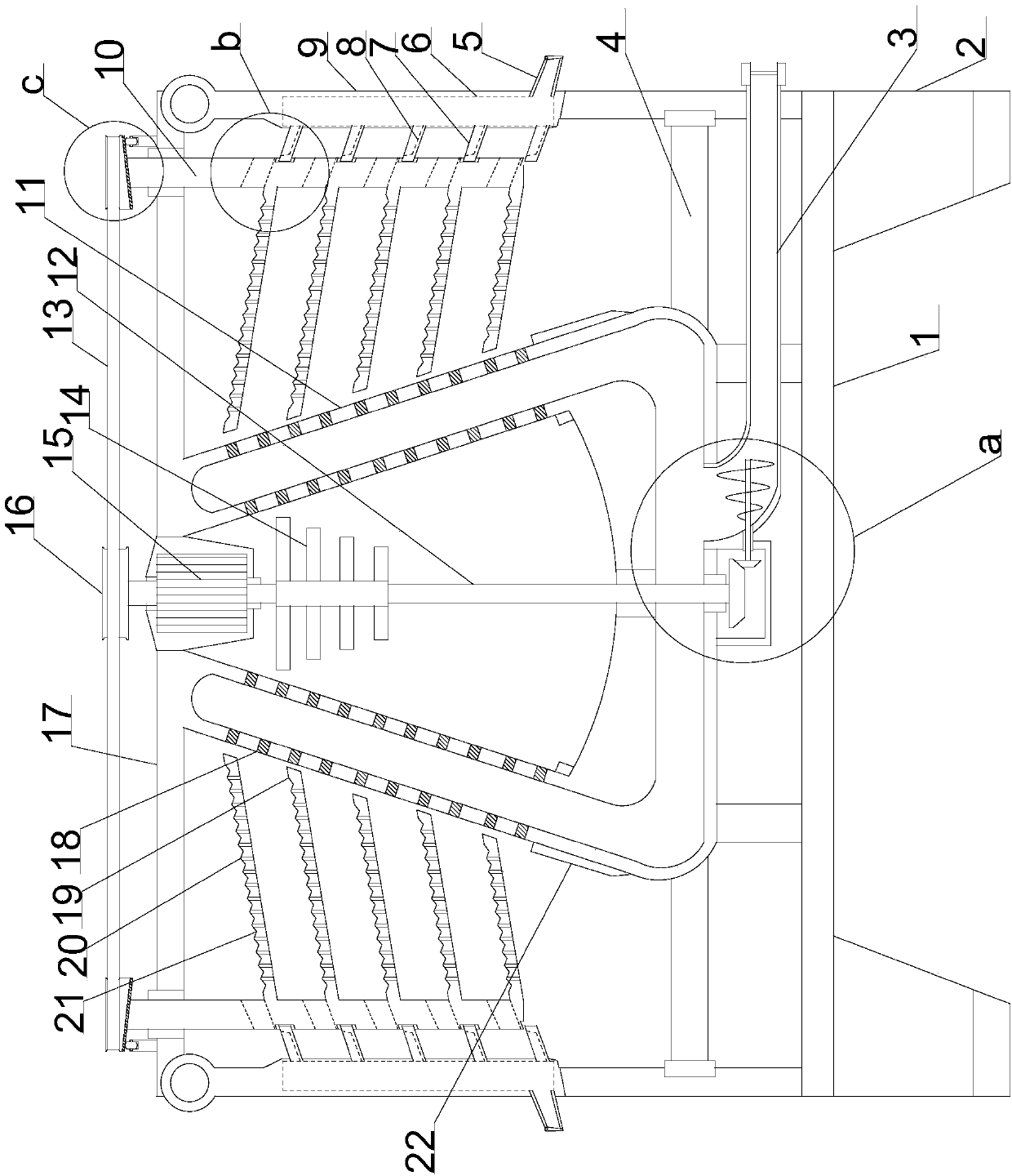
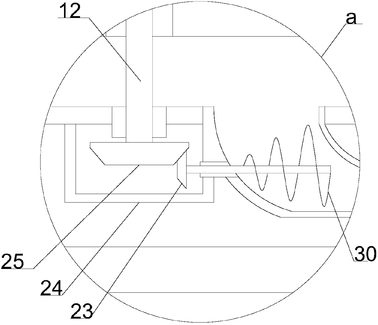
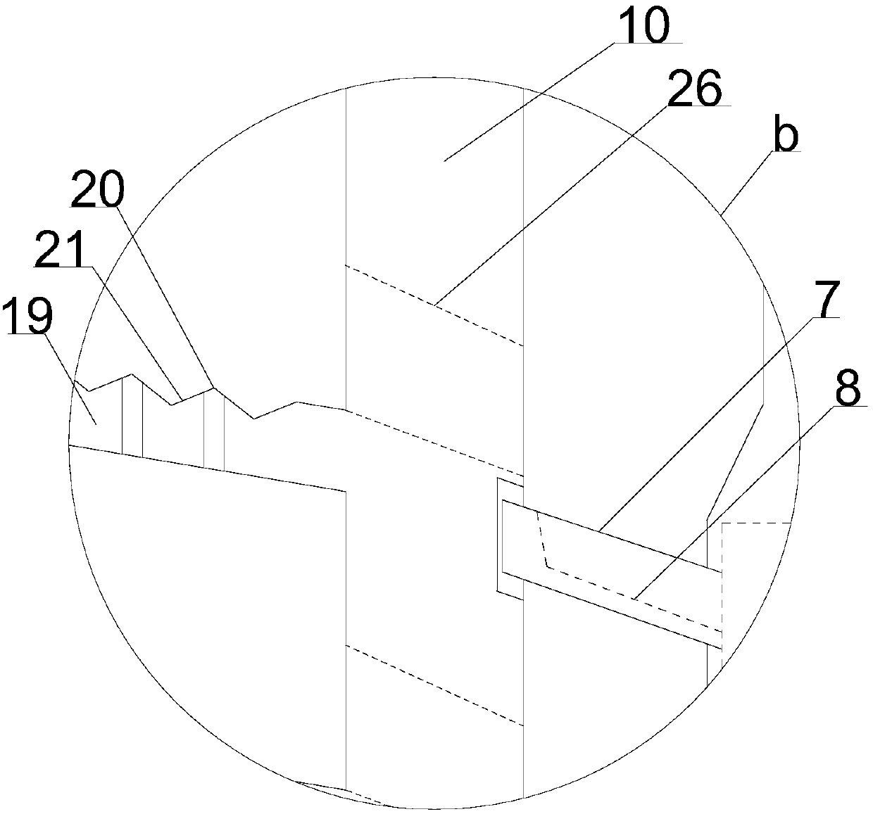
[0020] see Figure 1~5 , in an embodiment of the present invention, a feed granulation rapid drying and discharging device includes a support installation plate 1, the lower end of the support installation plate 1 is symmetrically provided with support installation columns 2, and the lower ends of the support installation columns 2 are all horizontal Inlaid with anti-slip rubber pads, the upper end of the support installation plate 1 is vertically provided wit...


PUM


Abstract

The invention discloses a quick drying and discharging device for feed granulation. The quick drying and discharging device for feed granulation comprises a supporting mounting plate, a supporting mounting barrel is vertically arranged at the upper end of the supporting mounting plate, and a distribution mounting barrel is vertically upward fixed to the middle of the lower end of the supporting mounting barrel through a horizontally arranged supporting mounting frame. A motor mounting barrel fixed in the middle of the upper end of the supporting mounting barrel in a vertically inlaid mode is provided with a driving motor, a plurality of sets of flow guide heat dissipation pipes inclined at the same angle are arranged on the outer sides of the distribution mounting barrel in cooperation with the driving motor upwards, the upper ends of the flow guide heat dissipation pipes are all connected with the top end of the supporting mounting barrel, a plurality of heat dissipation flow guide holes are evenly formed in the outer side of each flow guide heat dissipation pipe in a penetrating mode, and a transmission rotating shaft penetrating through the distribution mounting barrel is arranged at the lower end of the driving motor vertically downwards. The quick drying and discharging device for feed granulation has the advantages of novel design, multilayer movable drying, circulation turbulent flow blowing, smooth drying process, quick drying and discharging, good quality and the like.

Description

technical field [0001] The invention relates to feed production equipment, in particular to a feed granulation rapid drying discharge device. Background technique [0002] Feed mixing, stirring and granulation are three important steps in feed production. The drying of granulation is the best choice to ensure the packaging, transportation and storage of feed. Due to the direct stacking drying method, static drying or direct blowing drying, there are various problems in actual use. [0003] In order to solve the above problems, the present invention is proposed, which overcomes the problems of the currently used feed granulation drying device, due to the adoption of an open drying structure, which causes low drying efficiency and is easily polluted by the outside world, and solves the problems of the currently used feed granulation drying device. The drying device for granulation, due to the direct stacking drying method, the air circulation is difficult, resulting in long d...

Claims


Application Information

Patent Timeline
IPC IPC(8): F26B17/16F26B21/00F26B25/00F26B25/04A23N17/00
CPCF26B17/16A23N17/00F26B21/004F26B25/002F26B25/04F26B2200/08
Inventor 季梅
Owner 季梅
Why Eureka
Try Eureka