
S intering end point position control method and system

A technology of sintering end point and sintering machine, which is applied in the direction of furnace control device, furnace type, furnace, etc., can solve the problems of sintering process fluctuation, sintering production process instability, and affecting sintering quality, so as to improve quality and improve sintering production Efficiency, the effect of stabilizing the production process

Active Publication Date: 2018-04-20
SHANXIN SOFTWARE CO LTD
View PDF4 Cites 4 Cited by
  • Summary
  • Abstract
  • Description
  • Claims
  • Application Information

AI Technical Summary

Problems solved by technology

However, due to the influence of various factors such as ignition temperature, material layer thickness and sintering machine speed, it is difficult to ensure that the control is near the preset fixed value, which seriously affects the quality of sintering ore
[0004] At present, the control of the sintering end point is mainly realized by simply adjusting the speed of the sintering machine, and the operation of changing the machine speed to adjust the sintering end point will bring about such as the speed of the feeder machine, the speed of the ring cooler, the speed of the plate feeder and A series of corresponding changes such as changes in the material level of the bottom material trough and the change of the material level of the mixing material trough, improper control will lead to greater fluctuations in the sintering process
For such difficult-to-control links, if manual adjustments are still made based on subjective judgments, it will bring great instability to the sintering production process.

Method used


Image

  • S intering end point position control method and system
  • S intering end point position control method and system
  • S intering end point position control method and system

Examples


Embodiment Construction

[0050] In order to make the object, technical solution and advantages of the present invention clearer, the present invention will be further described in detail below in conjunction with the accompanying drawings and embodiments. It should be understood that the specific embodiments described here are only used to explain the present invention, not to limit the present invention.

[0051] The method for controlling the sintering end position provided in the embodiment of the present application includes the following steps:

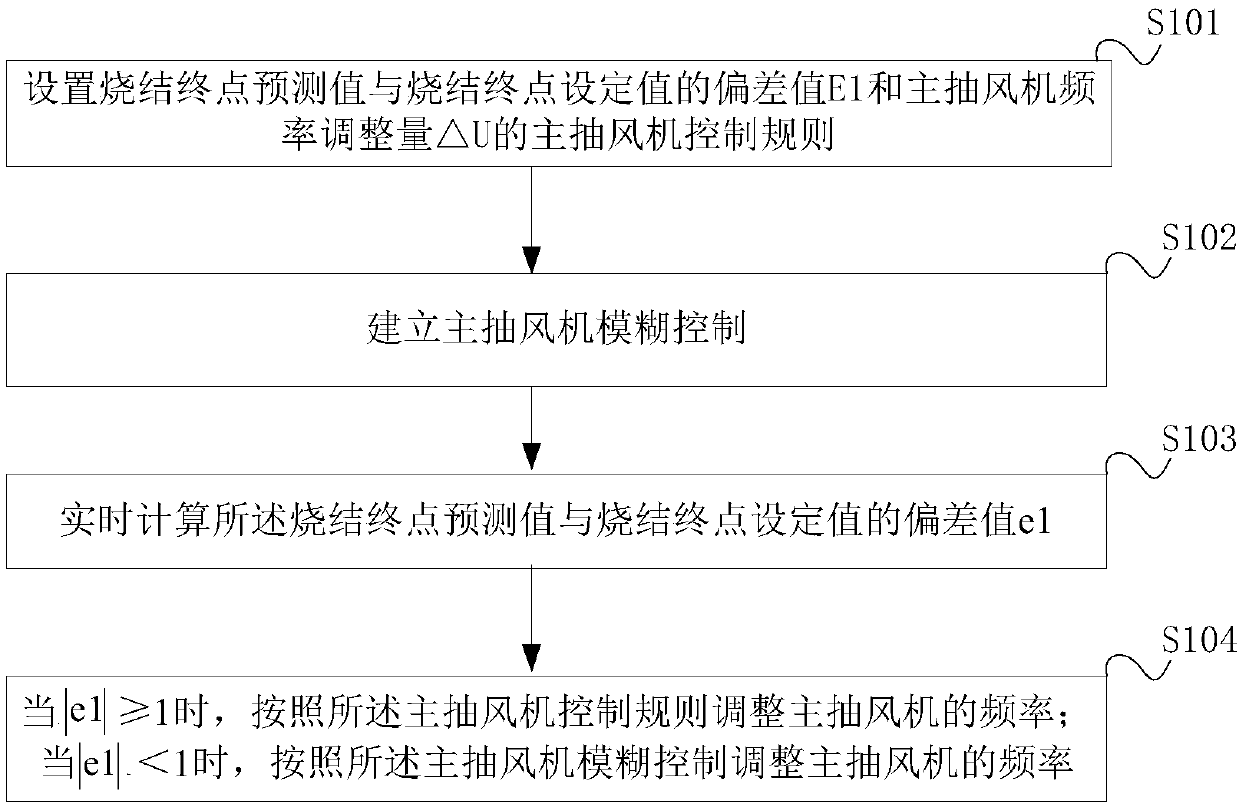
[0052] Set the deviation value E1 between the predicted value of the sintering end point and the set value of the sintering end point and the main exhaust fan frequency control rule of the main exhaust fan frequency adjustment ΔU, and establish the fuzzy control of the main exhaust fan frequency;

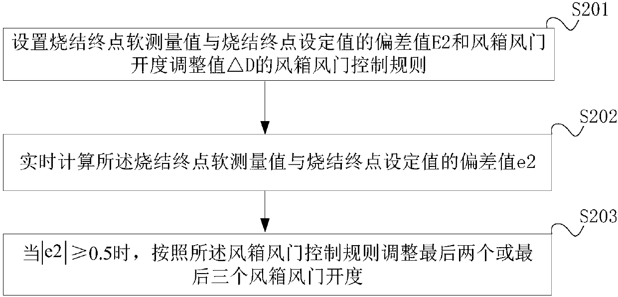
[0053] Set the deviation value E2 between the soft measurement value of the sintering end point and the set value of the sintering end point and the bellows d...


PUM


Abstract

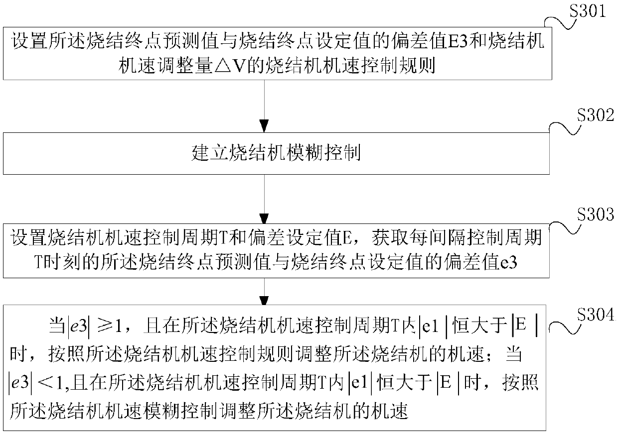
The invention provides a sintering end point position control method and system. The method comprises the steps of setting a deviation value E1 of the sintering end point prediction value and the sintering end point set value and a main exhaust fan frequency control rule of the main exhaust fan frequency adjustment amount delta U, and establishing a main exhaust fan frequency fuzzy control; setting a deviation value E2 of the sintering end point soft measurement value and the sintering end point set value and an air box air door control rule of the air box air door opening degree adjusting value delta D; and setting the deviation value E3 of the sintering end point prediction value and the sintering end point set value and a sintering machine machine speed control rule of the sintering machine machine speed adjustment amount delta V, establishing a sintering machine machine speed fuzzy control, and according to the deviation values e1 and e2 monitored in real time, an overall coordination control of the sintering process state is realized through the operations that the controls on the main exhaust fan frequency and the air box air door opening degree serve as a main control, and the control on the sintering machine machine speed serves as an auxiliary control. According to the sintering end point position control method and system, the sintering end position can be facilitatedto be stably controlled to be close to a set value, the sintering production process is stabilized, and sintering production efficiency is improved.

Description

technical field [0001] The present application relates to the technical field of iron ore sintering, in particular to a method and system for controlling the position of a sintering end point. Background technique [0002] Iron ore sintering refers to mixing various powdery iron-containing raw materials with an appropriate amount of fuel and flux, and adding an appropriate amount of water. After mixing, they are placed on a sintering trolley and roasted to cause a series of physical and chemical changes to form Sintered ore that is easy to smelt. Iron ore sintering is an important production process in modern iron and steel enterprises, which provides the blast furnace with a charge with a certain particle size, strength and stable chemical composition. [0003] The sintering process is a typical complex industrial process, and the position of the sintering end point is an important parameter to characterize the state of the sintering process. Controlling the position of t...

Claims


Application Information

Patent Timeline
Patent Type & Authority Applications(China)
IPC IPC(8): F27B21/14
CPCF27B21/00F27D19/00
Inventor 汪春鹏谭玉倩康凯刘爱强任伟陈新峰张军方光深许文菊李振刚展杰董京帅
Owner SHANXIN SOFTWARE CO LTD
Learn More