
A high-tower test system for terminal sensitive detectors

A test and detector technology, applied in direction control systems, weapon accessories, offensive equipment, etc., can solve the problems of staying, not involving target recognition and target hit simulation, and difficulty in ensuring test accuracy, reducing test costs, The test process is intuitive and the effect of reducing the complexity of the test

Active Publication Date: 2019-09-20
芜湖博高光电科技股份有限公司
View PDF9 Cites 0 Cited by
  • Summary
  • Abstract
  • Description
  • Claims
  • Application Information

AI Technical Summary

Problems solved by technology

For the half-in-the-loop simulation system researched in open literature such as "Millimeter Wave AC Radiometer Half-in-the-loop Simulation System Design", the target radiation characteristics are simulated by a certain mathematical model simulation to simulate the actual measurement environment. It is only a static test system, and the test accuracy Difficult to guarantee
However, there are relatively few public documents on the high-tower test technology of terminal sensitive detectors, and there has not been a detailed introduction to the mature high-tower test system so far.
Although the conventional high-tower test technology mentioned in relevant documents such as "Ka-band AC radiometer and its high-tower experiment" can guarantee the accuracy of the test results to a certain extent, it only stays at the end of the millimeter wave. Detector index test and target detection stage, does not involve target recognition and target hit simulation, etc.

Method used


Image

  • A high-tower test system for terminal sensitive detectors
  • A high-tower test system for terminal sensitive detectors
  • A high-tower test system for terminal sensitive detectors

Examples


Embodiment Construction

[0024] Hereinafter, exemplary embodiments of the present invention will be described in detail with reference to the accompanying drawings. The description of the exemplary embodiments is for exemplary purposes only, and is by no means a limitation to the present invention and its application or usage.

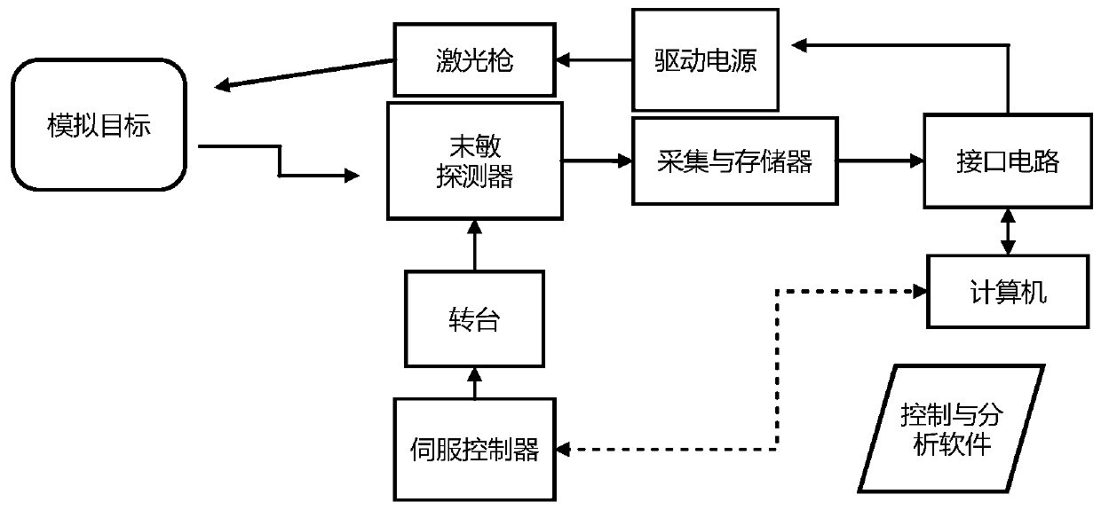
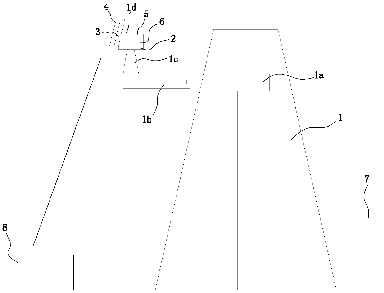
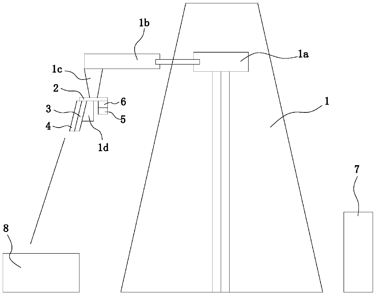
[0025] Reference figure 1 , figure 2 with Figure 4 As shown, according to the illustrated embodiment of the present invention, a high-tower test system for a terminal sensitive detector is provided, which includes a high tower 1, a target detection system, a target strike system, and a host 7 and a simulated target 8 set on the ground. , A liftable turntable 2 is installed on the high tower 1, and the target detection system and the target strike system are installed on the turntable 2. The turntable 2 is provided with a rotary drive device 1c that drives the target detection system and the target strike system to rotate around a rotation axis, The transmitting ends of the tar...


PUM


Abstract

The invention relates to the field of performance study of missile-borne millimeter-wave radiometers, in particular to a test system for high-tower testing of a terminal-sensitive detector. The test system for high-tower testing of the terminal-sensitive detector comprises a high tower, a target detection system, a target striking system, a host computer and a simulated target, wherein the host computer and the simulated target are arranged on the ground. A liftable rotary table is mounted on the high tower. The target detection system and the target striking system are mounted on the rotary table. The transmitting terminal of the target detection system and the transmitting terminal of the target striking system face the ground at the same inclination angle. A control and analysis moduleis arranged in the host computer. According to the test system for high-tower testing of the terminal-sensitive detector, a warhead hit is simulated through laser dotting, so that compared with a gunlaunching test, the test cost is greatly reduced, and the test complexity is lowered; the test process is more visual, and testing data can ensure the accuracy of test results; and the test system isa dynamic simulation test system, has a static parameter testing function, can inspect the overall performance of the detector more comprehensively, and is more practical.

Description

Technical field [0001] The invention relates to the field of research on the performance of a bomb-borne millimeter wave radiometer, in particular to a high-tower test system for a terminal sensitive detector. Background technique [0002] The related technical background of the present invention is described below, but these descriptions do not necessarily constitute the prior art of the present invention. [0003] With the continuous development of millimeter wave technology, millimeter wave detectors have also been widely used in precision guidance and remote sensing technology. The millimeter wave radiometer is a passive detection technology, which is often used as a terminal sensitive detector for missile guidance in modern warfare. [0004] In order to know the detection capability and overall performance of the developed millimeter-wave terminal-sensitive detectors and the target recognition effect, it is generally necessary to perform related performance tests on the millime...

Claims


Application Information

Patent Timeline
Patent Type & Authority Patents(China)
IPC IPC(8): F41G7/00
Inventor 苏刚李睿霖高磊马军许建中金海涛
Owner 芜湖博高光电科技股份有限公司
Learn More