Method for establishing shaping limit graph of thin wall tubing and apparatus thereof

A technology of forming limit map and thin-walled pipes, which is used in measuring devices, analyzing materials, and testing the strength of materials by applying stable tension/pressure. perfection etc.

Active Publication Date: 2018-04-20
TAIYUAN UNIV OF TECH
View PDF4 Cites 7 Cited by
  • Summary
  • Abstract
  • Description
  • Claims
  • Application Information

AI Technical Summary

Problems solved by technology

One is to obtain different stress states by changing the length of the bulging zone of the pipe, but this method can only establish the right side of the FLD. From the beginning to the end of the deformation of the pipe, it is gradually carried out from the plane strain to the two-way tensile stress. transition, and for some pipes with low plasticity, the strain path deviates from the plane strain state very small and the rupture has already occurred, and the uniaxial tensile stress state needs to be obtained by uniaxial stretching of the axial specimen, in fact, it should be obtained through the hoop Uniaxial tension of the specimen to obtain

Method used


Image

  • Method for establishing shaping limit graph of thin wall tubing and apparatus thereof
  • Method for establishing shaping limit graph of thin wall tubing and apparatus thereof
  • Method for establishing shaping limit graph of thin wall tubing and apparatus thereof

Examples


Embodiment Construction

[0012] The technical solutions of the present invention will be further described in more detail below in conjunction with specific embodiments. Apparently, the described embodiments are only some of the embodiments of the present invention, not all of them. Based on the embodiments of the present invention, all other embodiments obtained by persons of ordinary skill in the art without creative efforts shall fall within the protection scope of the present invention.

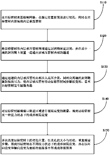
[0013] refer to figure 1 , figure 1 It is a schematic flowchart of a method for establishing a forming limit diagram of a thin-walled pipe provided by the present invention. The steps of the method include:

[0014] S110: Draw a grid on the surface of the target pipe, cut holes at the specified position according to the preset, and load the inner layer pressure-bearing pipe inside the target pipe.

[0015] Cut holes in the specified area of ​​the thin-walled target pipe to be measured according to the preset ...


PUM


Abstract

The invention discloses a method for establishing a shaping limit graph of a thin wall tubing and an apparatus thereof. The method is characterized in that symmetrical apertures are arranged on a surface of a target tubing, bulging is generated under effect of hydraulic pressure in a bearing tubing at an internal layer, by changing shapes, sizes and positions of the apertures, and shaping limit ofthe target tubing under all stress states in a scope from unidirectional stretching to bidirectional stretching can be obtained; under effect of hydraulic pressure in the bearing tubing at the internal layer, the target tubing and the bearing tubing at the internal layer are subjected to synchronous expansion, friction effect between two tubing is little, and an inaccurate result cannot be generated due to friction influence of the target tubing. Compared with a method for axially applying pressure or pulling force, the method of the invention is simple, closed loop servo control of the internal pressure and axial force are not required, the shapes, sizes and positions of the apertures are required to be designed in a reasonable mode, and the appropriate bearing tubing at the internal layer is selected as a support.

Description

technical field [0001] The invention relates to the field of hydroforming of pipes, in particular to a method and device for establishing a forming limit diagram of thin-walled pipes. Background technique [0002] The forming limit of the sheet metal indicates the maximum deformation that can be achieved before plastic instability occurs. The main instability modes of the sheet metal include necking, fracture, and wrinkling. Over the years, the forming limit diagram (Forming Limit Diagram, FLD) has been widely used to describe the formability of sheet metal, and there are several different experimental methods to establish the forming limit diagram of flat sheet metal. By uniaxially stretching the sheet, the forming limit of the tensile-compressive strain region (left side of the FLD) can be studied. When the width of the tensile specimen is wide, it is possible to realize the deformation of the plane strain state, so the uniaxial tensile It is only applicable to the measur...

Claims


Application Information

Patent Timeline
IPC IPC(8): G01N3/06G01N3/12
CPCG01N3/068G01N3/12G01N2203/0017G01N2203/0048G01N2203/0075G01N2203/0274G01N2203/0647
Inventor 崔晓磊林鹏池成忠林飞
Owner TAIYUAN UNIV OF TECH
Why Eureka
Try Eureka