Testing device and method for simulating ground loss triggered by subway shield tunnel stratum cavity

A technology of formation cavity and test device, which is applied in the direction of soil material testing and material inspection products, can solve the problem of inaccurate reflection of the change process of formation loss, centrifugal field radial and tangential error particle size effects, boundary effects, and To solve problems such as strata, achieve accurate and intuitive stratum loss change data, stabilize the external environment, and reduce the workload

Inactive Publication Date: 2016-01-06
SOUTHWEST JIAOTONG UNIV
View PDF7 Cites 15 Cited by
  • Summary
  • Abstract
  • Description
  • Claims
  • Application Information

AI Technical Summary

Problems solved by technology

[0004] 1. At present, most of the research is still on the research of surface subsidence. There is no simple, accurate and intuitive method for monitoring the particle displacement in the stratum caused by stratum voids, so the relationship between the stratum loss and the deformation of the upper soil cannot be obtained. There is no effective experimental data for studying the mechanism of formation loss
[0005] 2. Due to the principle of the test, there are problems such as centrifugal field radial and tangential errors, particle size effects, boundary effects, etc., so that the experimental results deviate from the prototype and cannot accurately reflect the change process of formation loss
[0006] 3. Although there have been some simulations of formation loss, there are quite a lot of simulation problems, and the system is relatively scattered and messy, and a sound and effective system has not been formed.
And the test efficiency is not high

Method used


Image

  • Testing device and method for simulating ground loss triggered by subway shield tunnel stratum cavity
  • Testing device and method for simulating ground loss triggered by subway shield tunnel stratum cavity
  • Testing device and method for simulating ground loss triggered by subway shield tunnel stratum cavity

Examples


Embodiment Construction

[0036] The present invention will be described in detail below in conjunction with specific embodiments.

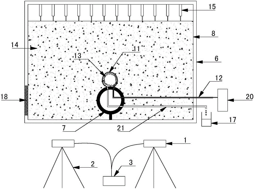
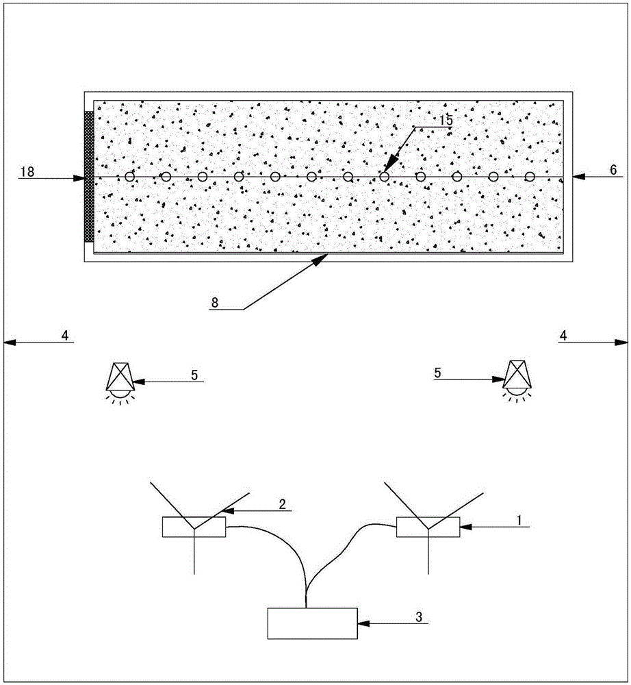
[0037] like Figure 1-3 As shown, a test device for simulating formation loss caused by ground voids in subway shield tunnels, including: a visual recognition system, a model box system, a polyamide liquid bag 11, a first conduit 12 connected to the polyamide liquid bag 11, and a second Two conduits 21, a container 17 corresponding to the second conduit 21, a resistance wire 13 arranged inside the polychloramine liquid bag 11, a heating control device 20 connected to the resistance wire;

[0038]The visual recognition system includes: a real-time monitoring camera 1, a fixed bracket 2, and an acquisition calculation module 3. The real-time monitoring camera 1 is used to capture video images of the monitoring interface, and transmit the video images to the acquisition calculation module 3 for analysis and calculation to obtain the displacement of the point of interest The...


PUM


Abstract

The invention discloses a testing device and method for simulating ground loss triggered by a subway shield tunnel stratum cavity. The testing device comprises a visual identification system, a model box system, a poly-chloramine sac (11), a first guide pipe (12) and a second guide pipe (21) which are communicated with the poly-chloramine sac (11), a container (17) corresponding to the second guide pipe (21), a resistance wire (13) arranged inside the poly-chloramine sac (11) and a heating control device (20) connected with the resistance wire, wherein the visual identification system comprises a real-time monitoring camera (1), a fixing support (2) and an acquisition and calculation module (3); the real-time monitoring camera (1) is used for shooting a video image of a monitoring interface; the video image is transmitted to the acquisition and calculation module (3) to be analyzed and calculated so as to obtain displacement data of an interest point; the testing device further comprises a purdah (4) for covering the whole testing device and light sources (5) fixed in position. According to the device, the sedimentation of each particle in the developing process can be monitored in real time.

Description

technical field [0001] The invention belongs to the technical field of underground engineering tests, and in particular relates to a test device and method for simulating formation losses caused by formation voids in subway shield tunnels. It can simulate the surface settlement and the subsequent stratum loss process caused by stratum voids caused by over-excavation in shield construction, providing a basis for construction and design optimization. Background technique [0002] Today, the subway has developed rapidly due to its advantages of economy, comfort, convenience, and speed, and the shield tunneling method, as the most effective method for subway construction, has also developed rapidly. After development, it has been basically sound, forming a complete set of sound technical theories. However, the disturbance of the surrounding stratum caused by the construction process, resulting in the release of stratum pressure and stratum deformation, still exists. These prob...

Claims


Application Information

Patent Timeline
IPC IPC(8): G01N33/24
Inventor 方勇汪辉武徐晨郭建宁杨志浩
Owner SOUTHWEST JIAOTONG UNIV
Why Eureka
Try Eureka