Method and apparatus for measuring far field pattern of antenna

A technology of directional diagram and antenna, applied in the direction of antenna radiation pattern, etc., can solve the problems of narrow measurement frequency band, low test efficiency and difficult installation of rectangular opening waveguide antenna probe

Active Publication Date: 2018-04-20
BEIJING UNIV OF POSTS & TELECOMM
View PDF7 Cites 4 Cited by
  • Summary
  • Abstract
  • Description
  • Claims
  • Application Information

AI Technical Summary

Problems solved by technology

[0006] However, with the development of communication technology and radar technology, the frequency band of the antenna to be tested is getting wider and larger, and the physical size is getting bigger and bigger. However, the measurement frequency band of the rectangular aperture waveguide antenna probe is narrow, and it needs to be constantly replaced when measuring the broadband antenna. The measurement probe can meet the measurement requirements, and it is large in size in the low frequency band, so it is not easy to install
In addition, since the rectangular opening waveguide antenna has only one feed point, it needs to be mechanically rotated by 90° and measured twice to measure the two polarization components of the electric field during the measurement process, and the test efficiency is low

Method used


Image

  • Method and apparatus for measuring far field pattern of antenna
  • Method and apparatus for measuring far field pattern of antenna
  • Method and apparatus for measuring far field pattern of antenna

Examples


Embodiment Construction

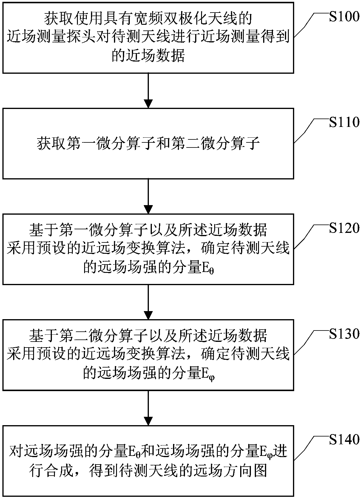
[0054] At present, the spherical near-field measurement system generally uses a rectangular aperture waveguide antenna as the sampling probe for near-field measurement. Through near-field sampling, the near-field data of the antenna to be tested is collected, and then the near-field data of the antenna to be tested is obtained through the spherical near-far field transformation algorithm. Far-field radiation characteristics.

[0055] The basis of spherical near and far field transformation is the spherical wave eigenmode obtained from Maxwell's equations. Using the spherical wave eigenmodes of the near field and the far field, the near and far fields of the antenna under test can be respectively expanded using the mode expansion method Expanding, connecting the near-field and far-field is the invariance of the expansion coefficient of the same mode with the propagation distance. Therefore, if you want to obtain the transformation from the near-field to the far-field of the ante...


PUM


Abstract

Embodiments of the invention provide a method and apparatus for measuring a far field pattern of an antenna, an electronic device, a storage medium, and a measurement system. A near field measurementprobe having a wideband dual polarized antenna is used. The wideband dual polarized antenna includes a first port and a second port. The method comprises the steps of acquiring near field data obtained by near field measurement of an antenna to be measured by using the near field measurement probe; acquiring a first differential operator and a second differential operator; determining an E[theta]component and an E[phi] component of the far field strength of the antenna to be measured respectively based on the first differential operator representing probe characteristics of the first port andthe second differential operator representing probe characteristics of the second port and the near-field data by using a preset near-far field transformation algorithm; and synthesizing the E[theta]component and the E[phi] component of the far field strength to obtain a far field pattern of the antenna to be measured. With the above scheme, it is possible to improve the test efficiency while certain test accuracy is satisfied.

Description

technical field [0001] The invention relates to the technical field of spherical near-field measurement, in particular to a method and device for measuring the far-field pattern of an antenna. Background technique [0002] In recent years, with the wide application of antennas in communication systems, navigation systems, radar systems and other fields, antenna measurement technology has developed rapidly. The far-field measurement of the antenna is performed in the far-field area that satisfies the test distance of the far-field of the antenna, so as to directly obtain the radiation characteristics of the antenna. However, with the development of communication technology, there are more and more large-aperture antennas, and the electromagnetic environment is becoming more and more complex, which makes the realization conditions of far-field measurement more and more difficult to meet, thus limiting the development of far-field measurement technology. [0003] Compared with...

Claims


Application Information

Patent Timeline
Patent Type & Authority Applications(China)
IPC IPC(8): G01R29/10
Inventor 王卫民刘元安李梦任宇鑫吴永乐于翠屏黎淑兰苏明
Owner BEIJING UNIV OF POSTS & TELECOMM
Why Eureka
Try Eureka