Method for correcting misplaced partial image splicing

A local image and sub-image technology, applied in image analysis, graphic image conversion, image data processing, etc., can solve problems such as high cost and maintenance, difficult image registration, speed and real-time impact of stitching

Active Publication Date: 2018-04-20
北京天睿空间科技股份有限公司
View PDF4 Cites 20 Cited by
  • Summary
  • Abstract
  • Description
  • Claims
  • Application Information

AI Technical Summary

Problems solved by technology

[0006] The image registration method based on the frequency domain is simple and accurate, but this method generally requires a relatively large overlapping ratio, usually requiring a 50% overlapping ratio between the registered images. If the overlapping ratio is too small, it is easy to cause Misestimation of the translation vector, making image registration difficult
Under the engineering requirements of large-scale panoramic stitching, to achieve this condition that requires a relatively large overlapping ratio, the number of cameras that need to be provided is almost doubled, which has high requirements for hardware cost and maintenance. At the same time, too many The number of cameras will also have a great impact on the splicing rate and real-time performance
[0007] The method based on gray level similarity overcomes the shortcomings of the above-mentioned image registration method based on the frequency domain. The idea adopted by it is intuitive, and the calculation amount and accuracy can meet the engineering requirements. However, this method still has certain problem

Method used


Image

  • Method for correcting misplaced partial image splicing
  • Method for correcting misplaced partial image splicing
  • Method for correcting misplaced partial image splicing

Examples


Embodiment Construction

[0077] The present invention will be further described below in conjunction with the accompanying drawings and embodiments.

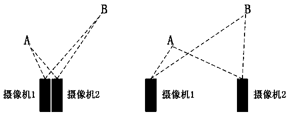
[0078] Such as Figure 2-Figure 5 As shown, due to the large distance between cameras often occurs in practical engineering applications, it is necessary to provide a method for dynamic features of local areas to address the shortcomings of stitching and misalignment in panoramic images obtained by gray-level similar methods. Transformation correction method, so as to eliminate the misalignment, so that the stitched panoramic image meets the actual application requirements.

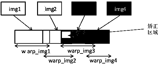
[0079] The key technical problem to be solved by the present invention is: how to eliminate the misalignment of the correction area under the condition of ensuring the connection between the image in the correction area and the image outside the correction area.

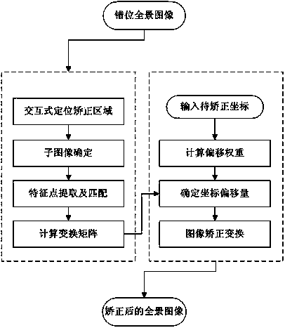
[0080] To solve this key technical problem, the present invention needs to complete three steps of dislocation area po...


PUM


Abstract

The invention relates to a method for correcting misplaced partial image splicing. The method comprises the following steps: in step 1, a misplaced spliced area in a panoramic spliced image with misplacement is determined, two spliced sub-images for splicing the area are determined, and the misplaced spliced area is taken as an area to be corrected; in step 2: exact matching is performed on the two spliced sub-images in the area to be corrected, a transformation matrix for exactly matching the two spliced sub-images in the area to be corrected, and initial coordinate offset used to correct themisplacement can be calculated accordingly; in step 3, weighted correction is performed, correction transformation is performed via weighted corrected coordinate offset, an offset weight coefficientis 1 in a central area of the area to be corrected and is 0 in an edge region of the area to be corrected, and the offset weight coefficient gradually transits between the area with the offset weightcoefficient being 1 and the area with the offset weight coefficient being 0. The method disclosed in the invention helps ensure that the correction transformation of a specified area is completed while that images in the area to be corrected and images beyond the area to be corrected are spliced is ensured, and a panoramic spliced image with eliminated misplacement is obtained.

Description

technical field [0001] The invention relates to a correction method for partial image splicing dislocation, in particular to a correction method for partial image splicing dislocation under panoramic splicing, and belongs to the technical fields of panoramic splicing, image registration and feature recognition. Background technique [0002] Image stitching technology is the technology of stitching several images with overlapping parts into a large seamless high-resolution image. One of the most widely used stitching methods in image stitching technology is panoramic stitching. After projecting onto a common surface for registration, all adjacent images are fused to finally generate a panorama. Therefore, the core technology of panorama stitching is image registration technology. [0003] The current image registration algorithms can basically be divided into two categories: methods based on frequency domain and methods based on gray level similarity. Among them, the method b...

Claims


Application Information

Patent Timeline
IPC IPC(8): G06T3/40G06T7/33
Inventor 吴刚侯文静郑文涛王国夫
Owner 北京天睿空间科技股份有限公司
Why Eureka
Try Eureka