Hollow coil winding jig

A technology of hollow coils and winding fixtures, which is applied in the manufacture of electrical components, inductors/transformers/magnets, circuits, etc., can solve problems such as high energy consumption, poor practicability, and burns, and achieve reduced processing difficulty, reduced costs, and energy saving The effect of the design

Inactive Publication Date: 2018-04-20
TANAC AUTOMATION
View PDF1 Cites 2 Cited by
  • Summary
  • Abstract
  • Description
  • Claims
  • Application Information

AI Technical Summary

Problems solved by technology

[0003] The above-mentioned heating method consumes a lot of energy and is prone to burn accidents
[0004] Secon

Method used


Image

  • Hollow coil winding jig
  • Hollow coil winding jig
  • Hollow coil winding jig

Examples


Embodiment Construction

[0092] The following are specific embodiments of the invention and in conjunction with the accompanying drawings, the technical solutions of the present invention are further described, but the present invention is not limited to these embodiments.

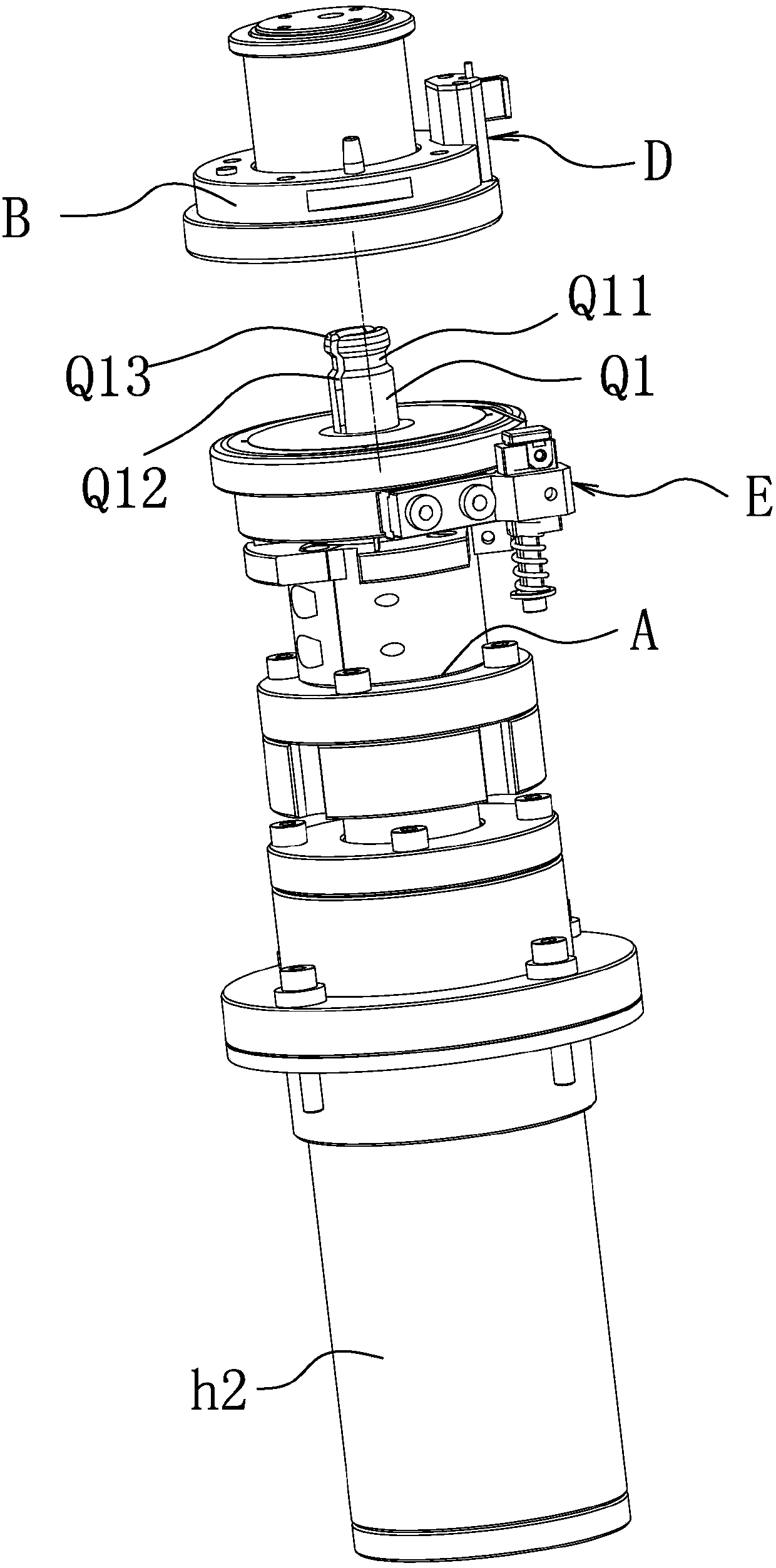
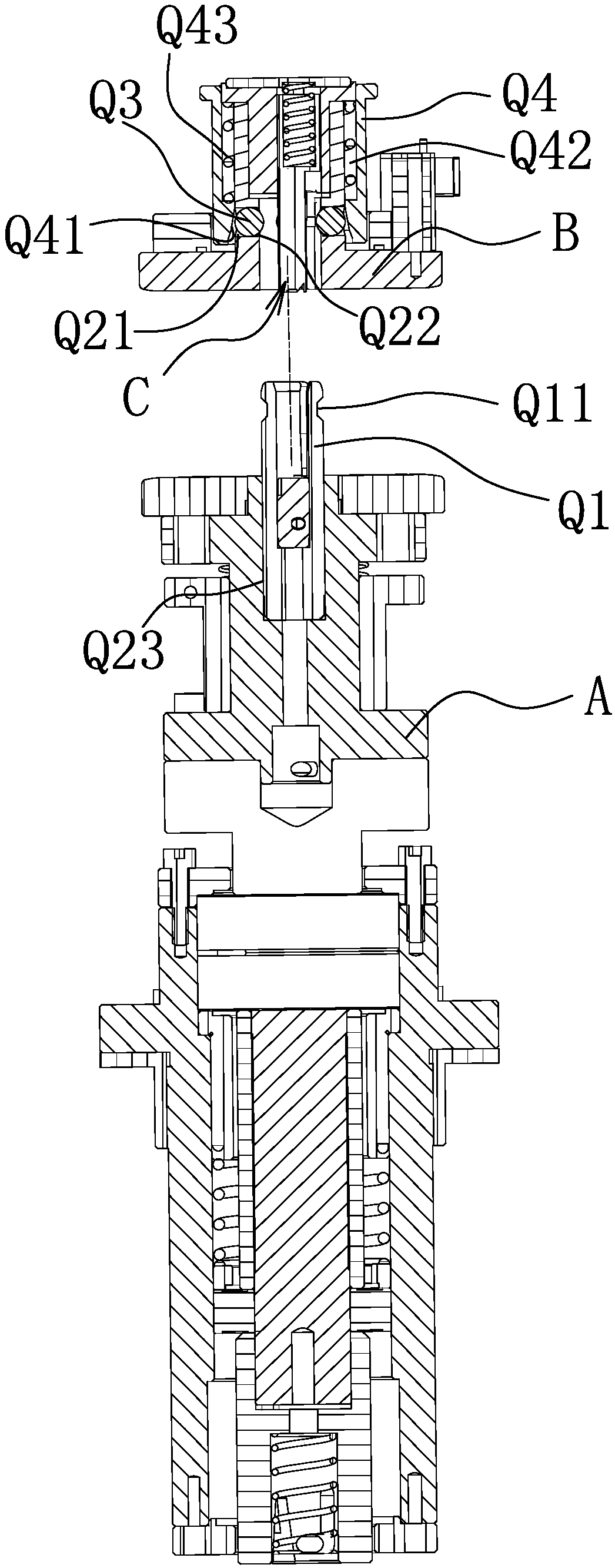
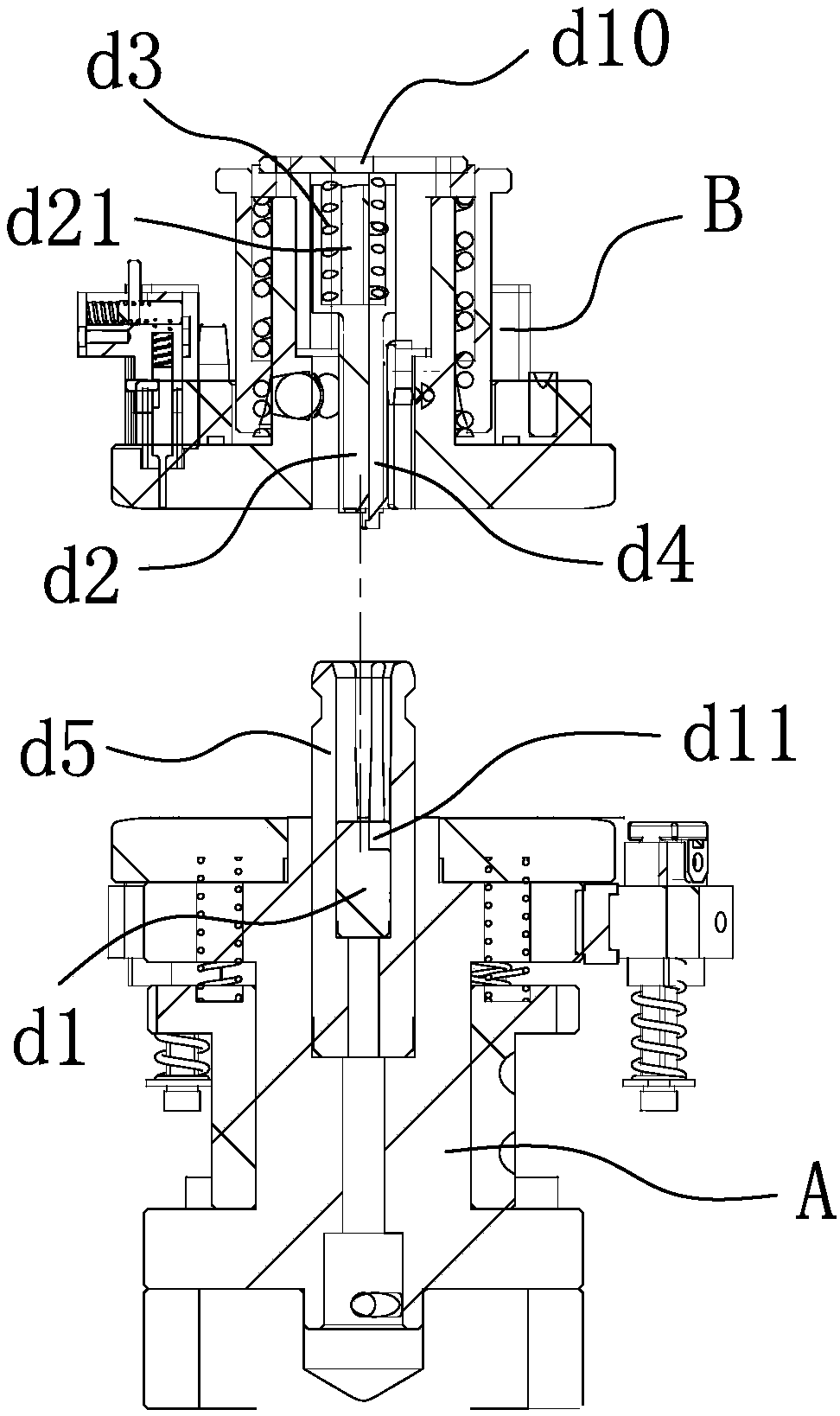
[0093] Such as Figure 1-2 and Figure 20 As shown, the hollow coil winding jig includes an upper jig B and a lower jig A located below the upper jig B. Between the upper jig B and the lower jig A, there is a The pierced inner wire head clamps the piercing mechanism C, and the outer edge of the upper jig B is provided with an outer wire end bending mechanism D that can force the outer wire end of the hollow coil to bend inward when the hollow coil is wound. The jig A or the upper jig B is provided with an outer wire end clamping and piercing mechanism E capable of clamping and piercing the outer wire end of the hollow coil.

[0094] Specifically, such as Figure 3-7 As shown, the internal thread end clamping and piercing mechan...


PUM


Abstract

The invention belongs to the technical field of winding equipment, and in particular relates to a hollow coil winding jig. It solves the problems of unreasonable design and the like in the prior art. The hollow coil winding jig includes an upper jig and a lower jig located below the upper jig, and an inner wire end clamp that can hold and puncture the inner wire end of the hollow coil is provided between the upper jig and the lower jig. The piercing mechanism is equipped with an outer wire head bending mechanism that can force the outer wire end of the hollow coil to bend inward when the hollow coil is wound on the outer edge of the upper jig, and is equipped on the lower jig or upper jig. The outer thread end clamping and piercing mechanism for holding and piercing the outer thread end of the hollow coil. The invention has the advantages of energy saving, safety and stronger practicability.

Description

technical field [0001] The invention belongs to the technical field of winding equipment, and in particular relates to a hollow coil winding jig. Background technique [0002] The current winding machine, when the coil winding is completed, generally heats the entire mold. After the mold is heated, the coil is heated. The insulating layer of the enameled wire of the heated coil is melted to connect the inner and outer rings together. . [0003] The above-mentioned heating method consumes a lot of energy and is prone to scald accidents. [0004] Secondly, the existing jigs do not have the function of bending the outer wire ends, so the practicability is poor. [0005] In order to improve the above-mentioned technical problems, for example, a Chinese patent discloses a winding fixture, application number 201520734127.6, which includes a winding fixing plate seat with a first surface and a second surface arranged in parallel, and a Several fixing pins are used for bending an...

Claims


Application Information

Patent Timeline
IPC IPC(8): H01F41/066H01F41/082H01F41/098B21F1/00
CPCH01F41/066B21F1/004H01F41/082H01F41/098
Inventor 李国锋范建良冯丙穆周理
Owner TANAC AUTOMATION
Why Eureka
Try Eureka