
Rotor structure for center ladder hole

A technology of rotor structure and stepped holes, which is applied in the direction of magnetic circuit shape/style/structure, magnetic circuit rotating parts, mechanical energy control, etc., to achieve the effect of reducing the heat generation of the rotor

Pending Publication Date: 2018-04-20
NANJING CIGU TECH CORP LTD
View PDF5 Cites 0 Cited by
  • Summary
  • Abstract
  • Description
  • Claims
  • Application Information

AI Technical Summary

Problems solved by technology

[0005] The natural frequency of the rotor is directly related to the stiffness of the bearing, its own mass distribution, and the structural size. Once the overall size of the rotor is basically determined, if the natural frequency is increased by adjusting the structural size, the effect will be limited.

Method used


Image

  • Rotor structure for center ladder hole
  • Rotor structure for center ladder hole
  • Rotor structure for center ladder hole

Examples


Embodiment Construction

[0019] The present invention will be further described below in conjunction with the accompanying drawings.

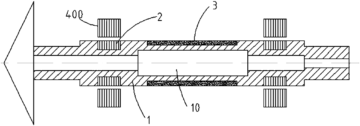
[0020] like figure 1 and figure 2 , the invention discloses a rotor structure with a central stepped hole, including a mandrel 1, a rotor silicon steel sheet 2 and a magnetic steel 3. The mandrel 1 includes an integrally formed and coaxially arranged shaft head 11, an intermediate shaft 12 and a shaft tail. 13. In the axial direction of the mandrel 1, a shaft hole 10 is provided through the shaft head 11, the intermediate shaft portion 12 and the shaft tail 13. The shaft hole 10 includes a first hole 101, a second hole 102 and a second hole. Three hole portions 103, the second hole portion 102 is located at the center of the intermediate shaft portion 12, the first hole portion 101 and the third hole portion 103 are symmetrically located on both sides of the second hole portion 102, and the first hole portion 101 is located from the shaft head The portion 11 extends...


PUM


Abstract

The invention discloses a rotor structure for a center ladder hole. The rotor structure comprises a mandrel, a rotor silicon steel sheet and magnet steel, wherein the mandrel comprises a shaft head part, a middle shaft part and a shaft tail part which are molded integrally and arranged coaxially; the mandrel is provided with a shaft hole passing through the shaft head part, the middle shaft part and the shaft tail part along an axle center direction; the shaft hole comprises a first hole part, a second hole part and a third hole part; the second hole part is positioned in the center of the middle shaft part; the first hole part and the third hole part are symmetrically positioned on two sides of the second hole part; the first hole part extends into the middle shaft part from the shaft head part; and the third hole part extends into the middle shaft part from the shaft tail part. According to the rotor structure, different shaft segments of a rotor assembly are reduced in weight reasonably, so that the aim of increasing the inherent frequency of the rotor assembly is fulfilled.

Description

Technical field: [0001] The invention relates to a rotor structure with a central stepped hole. Background technique: [0002] When designing the magnetic levitation motor rotor, it is necessary to avoid designing the working speed near its natural frequency to prevent resonance. With the development of the motor, its power and operating speed continue to increase. In order to increase the natural frequency of the rotor, there are usually two design directions: [0003] 1) The rotor is designed as a flexible shaft, and the working speed exceeds the first-order frequency, which is located between a certain two-order natural frequency, but the structure is complex and large; [0004] 2) It is still designed as a rigid shaft, and its speed is still lower than the first-order frequency, but at this time the structure of the rotor system needs to be adjusted. [0005] The natural frequency of the rotor is directly related to the stiffness of the bearing, its own mass distributi...

Claims


Application Information

Patent Timeline
Patent Type & Authority Applications(China)
IPC IPC(8): H02K1/22H02K7/00H02K7/09
CPCH02K1/22H02K7/003H02K7/09
Inventor 周亦骏胡思宁林英哲吴立华董继勇
Owner NANJING CIGU TECH CORP LTD
Learn More