Moving bracket for monitor

A technology for moving brackets and monitors. It is applied in the directions of machines/brackets, supporting machines, and components of color TVs. It can solve problems such as damage, inconvenient adjustment, and no camera protection, so as to avoid becoming dirty, old, and prolonged. Accurate effect of service life and camera range

Inactive Publication Date: 2018-04-24
STATE GRID TIANJIN ELECTRIC POWER +2
View PDF10 Cites 19 Cited by
  • Summary
  • Abstract
  • Description
  • Claims
  • Application Information

AI Technical Summary

Problems solved by technology

[0003] The patent No. 201621070554.X discloses "a video monitoring bracket that can be easily moved and folded", which realizes the functions of easy movement and use in places where it is inconvenient to install cameras or where it is not necessary to install cameras for a long time, but This patent does not protect the camera during the movement of the camera, so that the camera is easily damaged when it encounters obstacles during the movement, and although the rotation angle of the camera is changed by the universal deformation tube in this patent, when the camera is in the At a higher position, human hands cannot touch it, and the camera at a high position cannot be adjusted accurately. It is necessary to lower the height of the camera to adjust it. The accuracy of the range, and the adjustment is inconvenient

Method used


Image

  • Moving bracket for monitor

Examples


Embodiment Construction

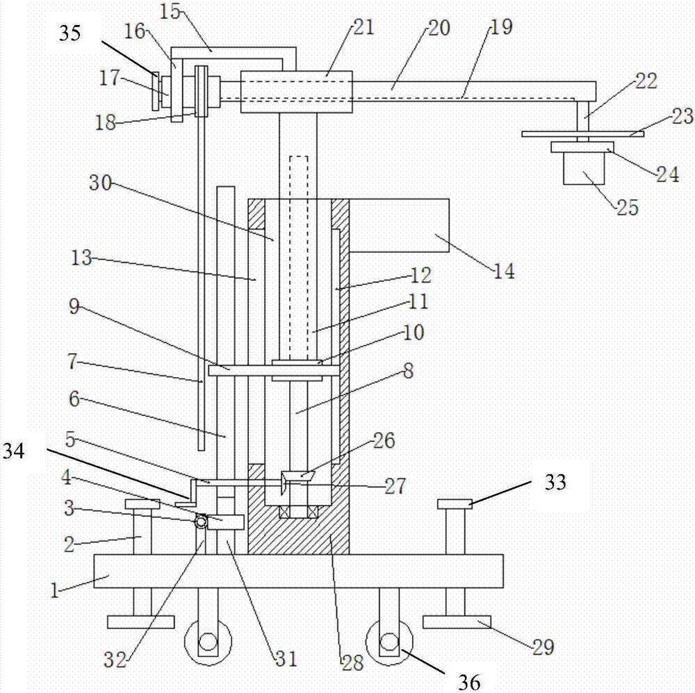
[0021] The technical solutions of the present invention will be described in further detail below in conjunction with the drawings and embodiments, but it should be known that these drawings are only designed for the purpose of explanation, and therefore are not intended to limit the scope of the present invention. Furthermore, unless otherwise indicated, the drawings are only intended to conceptually illustrate the architectural configurations described herein and are not necessarily drawn to scale.

[0022] In the description of the present invention, it should be noted that the terms "center", "upper", "lower", "left", "right", "vertical", "horizontal", "inner", "outer" etc. The indicated orientation or positional relationship is based on the orientation or positional relationship shown in the drawings, or the orientation or positional relationship that is usually placed when the product of the invention is used, and is only for the convenience of describing the present inve...


PUM


Abstract

The invention discloses a moving bracket for a monitor. The moving bracket for the monitor comprises a bottom base, and a support block. The top of the bottom base is provided with an installing block. The installing block is provided with a first groove with an upward opening. The bottom of the support block is provided with a camera. The top of one side wall of the first groove at the same sideas the camera is provided with a storage box. The top of the storage box is an opening structure. The first groove is internally provided with an internal spline shaft sleeve. The internal spline shaft sleeve is internally meshed with a spline shaft. The top of the internal spline shaft sleeve is provided with a fixing sleeve. The bottom in the fixing sleeve is provided with a sliding rail. The fixing sleeve is internally provided with a first screw rod. The bottom of the first screw rod is provided with a first sliding chute matched with the sliding rail. The left end and the right end of thefirst screw rod are stretched out from the interior of the fixing sleeve. The left end of the first screw rod is provided with a limiting plate. The moving bracket fixing device for the monitor is capable of protecting the camera, and preventing the camera from colliding to be damaged in a moving process. While the camera is located in an unused state, the camera can be stored, the dirty and agedcamera caused by the adhesion of dust is avoided, and the service life is prolonged.

Description

technical field [0001] The invention belongs to the technical field of video surveillance, and in particular relates to a stabilizing device for a mobile bracket of a monitor. Background technique [0002] Video surveillance, English Cameras and Surveillance, including front-end cameras, transmission cables, and video surveillance platforms. Cameras can be divided into network digital cameras and analog cameras, which can be used as front-end video image signal collection. A complete video surveillance system is composed of 5 parts: camera, transmission, control, display, record and registration. The camera transmits the video image to the control host through the network cable or coaxial video cable, and the control host distributes the video signal to each monitor and recording device, and simultaneously records the voice signal to be transmitted into the video recorder. By controlling the host computer, the operator can issue instructions to control the up, down, left, ...

Claims


Application Information

Patent Timeline
Patent Type & Authority Applications(China)
IPC IPC(8): F16M11/04F16M11/08F16M11/28F16M11/42H04N5/225
CPCF16M11/045F16M11/08F16M11/28F16M11/42H04N23/00
Inventor 蒋菱郭凌旭徐晟张杰张大衡
Owner STATE GRID TIANJIN ELECTRIC POWER
Why Eureka
Try Eureka