Radar detection method and device, storage medium and radar

A detection method and radar technology, applied in the field of radar, can solve problems such as long response time and long loop, and achieve the effect of improving the realism

Active Publication Date: 2018-04-24
LEISHEN INTELLIGENT SYST CO LTD
View PDF10 Cites 10 Cited by
  • Summary
  • Abstract
  • Description
  • Claims
  • Application Information

AI Technical Summary

Problems solved by technology

The disadvantage is that the response time of AGC is relatively long, usually tens of microseconds
Insufficient: The reaction time of APC is longe

Method used


Image

  • Radar detection method and device, storage medium and radar
  • Radar detection method and device, storage medium and radar
  • Radar detection method and device, storage medium and radar

Examples


Example Embodiment

[0055] Example one

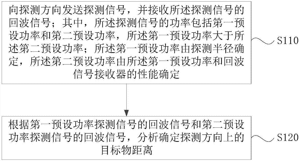
[0056] figure 1 It is a flowchart of the radar detection method provided in the first embodiment of the present invention. This embodiment is applicable to radar detection situations. The method can be executed by the radar detection device provided in the embodiment of the present invention, which can be implemented by software and / or hardware. Way to achieve, and can be integrated in the radar.

[0057] Such as figure 1 As shown, the radar detection method includes:

[0058] S110. Send a detection signal to the detection direction and receive an echo signal of the detection signal; wherein the power of the detection signal includes a first preset power and a second preset power, and the first preset power is greater than all The second preset power; the first preset power is determined by a detection radius, and the second preset power is determined by the first preset power and the performance of the echo signal receiver.

[0059] Among them, the detection sig...

Example Embodiment

[0074] Example two

[0075] Figure 5 It is a flowchart of the radar detection method provided in the second embodiment of the present invention. This embodiment is further optimized on the basis of the foregoing embodiment.

[0076] Such as Figure 5 As shown, the radar detection method includes:

[0077] S510: Obtain a detection radius, and determine a first preset power of the detection signal according to the detection radius.

[0078] Wherein, the method of obtaining the detection radius may be a method of inputting the detection radius by a worker, or a detection radius determined according to the performance of the radar signal transmitter. Wherein, the first preset power can also be input directly by the worker, and the detection radius can be determined according to the signal receiving period, or the detection radius can be determined according to other methods. This application does not specifically limit this.

[0079] S520: Determine a blind zone range for receiving the e...

Example Embodiment

[0090] Example three

[0091] Image 6 It is a schematic diagram of the structure of the radar detection device provided in the third embodiment of the present invention. Such as Image 6 As shown, the radar detection device includes:

[0092] The sending and receiving module 610 is configured to send a detection signal to the detection direction and receive an echo signal of the detection signal; wherein the power of the detection signal includes a first preset power and a second preset power, and the first A preset power is greater than the second preset power; the first preset power is determined by a detection radius, and the second preset power is determined by the first preset power and the performance of the echo signal receiver.

[0093] The target object distance determination module 620 is configured to analyze and determine the target object distance in the detection direction according to the echo signal of the first preset power detection signal and the echo signal of t...


PUM


Abstract

The embodiment of the invention discloses a radar detection method, a radar detection device, a storage medium and a radar. The method comprises the following steps: transmitting a detection signal tothe detection direction and receiving an echo signal of the detection signal, wherein the power of the detection signal comprises first preset power and second preset power, the first preset power ismore than the second preset power, the first preset power is determined by the detection radius and the second preset power is determined by the first preset power and the property of an echo signalreceiver; and analyzing and determining the target object distance in the detection direction according to the echo signal of the detection signal with the first preset power and the echo signal of the detection signal with the second preset power. By implementation of the technical scheme provided by the embodiment of the invention, the effect of improving the validity of the received echo signalcan be achieved.

Description

technical field [0001] Embodiments of the present invention relate to the technical field of radar, and in particular, to a radar detection method, device, storage medium, and radar. Background technique [0002] At present, in the long-distance measurement radar, a larger pulse transmission power is generally used to ensure that the echo signal generated by the long-distance target has sufficient energy. However, when detecting short-distance targets, the energy of the echo signal exceeds the upper limit of reception due to excessive power or high reflectivity of the target, causing the receiver to be saturated and unable to measure. [0003] The following two methods are often used to solve the above problems: [0004] 1. An automatic gain control circuit (Automatic Gain Control, AGC) is added to the receiving circuit to automatically adjust the receiver amplification gain according to the strength of the echo signal energy to keep the echo signal energy within the availa...

Claims


Application Information

Patent Timeline
IPC IPC(8): G01S17/08G01S7/484G01S7/486
CPCG01S7/484G01S7/4868G01S17/08
Inventor 沈俭王勇
Owner LEISHEN INTELLIGENT SYST CO LTD
Why Eureka
Try Eureka