Tilting head and tong-type tilting machine

A steel turning machine and steel turning technology, which is applied in the direction of workpiece manipulation, can solve the problems of inability to feed materials, limited turning angle, low work efficiency, etc., and achieves convenient installation and maintenance, improved use accuracy and life, rigidity and stability Improved effect

Active Publication Date: 2018-04-27
KEHE IND EQUIP TECH SHANGHAI
View PDF7 Cites 8 Cited by
  • Summary
  • Abstract
  • Description
  • Claims
  • Application Information

AI Technical Summary

Problems solved by technology

[0004] Aiming at the deficiencies in the prior art, the present invention provides a steel turning head and a pliers-type steel turning machine to ...

Method used


Image

  • Tilting head and tong-type tilting machine
  • Tilting head and tong-type tilting machine
  • Tilting head and tong-type tilting machine

Examples


Embodiment Construction

[0042] The following will clearly and completely describe the technical solutions in the embodiments of the present invention with reference to the accompanying drawings in the embodiments of the present invention. Obviously, the described embodiments are only some, not all, embodiments of the present invention. Based on the embodiments of the present invention, all other embodiments obtained by persons of ordinary skill in the art without making creative efforts belong to the protection scope of the present invention.

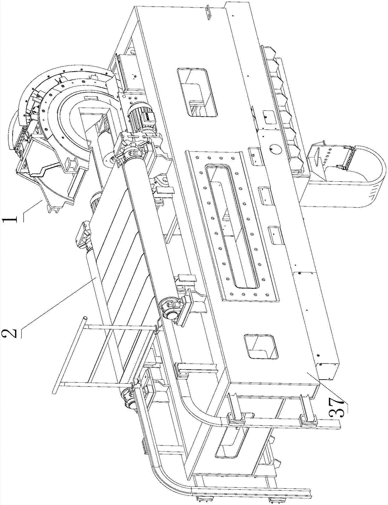
[0043] In actual production, the structural diagram of the steel turning machine when it is used in conjunction with the roller table is as follows: figure 1 Shown, rolling mill is positioned at the side of roller table 2, not drawn in the figure.

[0044] The present invention firstly provides a turning head 1, including a turning mechanism and a clamping mechanism.

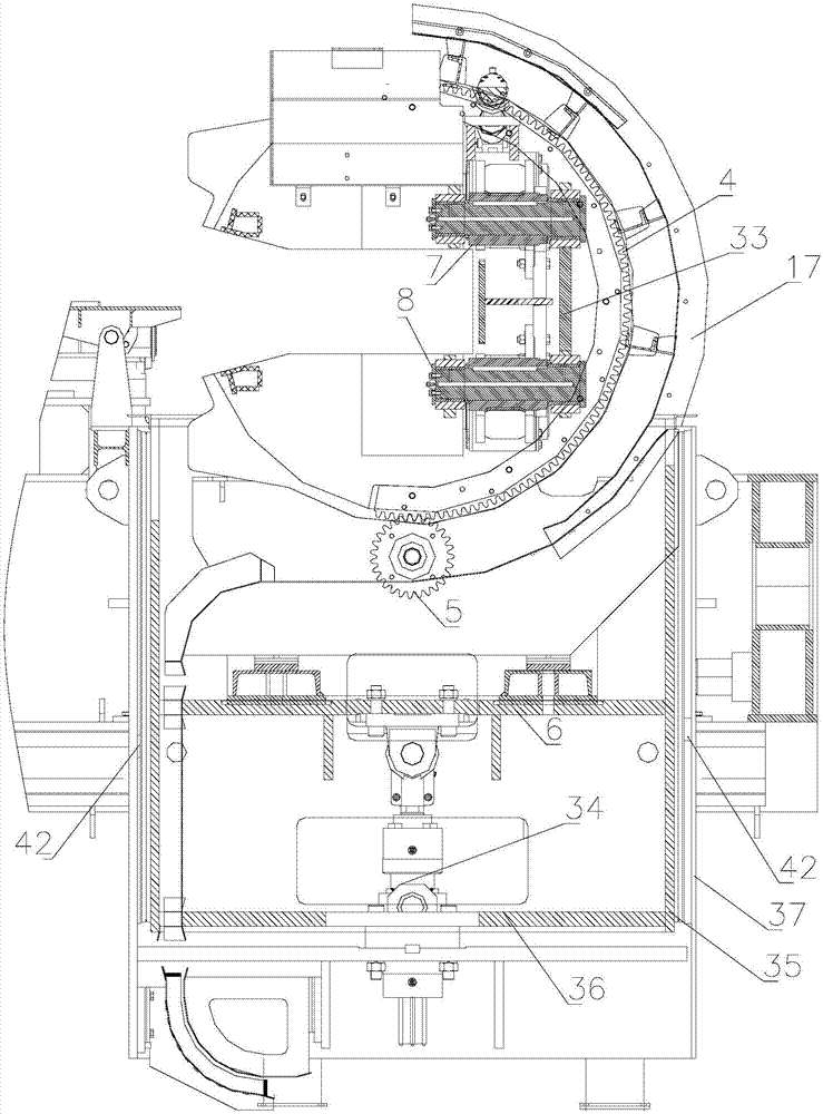
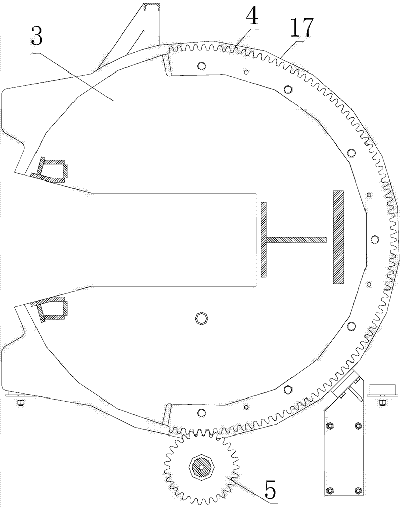
[0045] see figure 2 and 3 As shown, the turning mechanism includes a housing 3 , an arc ...


PUM


Abstract

A tilting head comprises an overturning mechanism and a clamping mechanism; the overturning mechanism comprises a casing, an arc-shaped rack and a first gear; the first gear is mounted on a base and is in shaft connection with a driving device; a through hole for placing a rolled material is formed in the casing; the arc-shaped rack is fixed on the edge of the side surface of the casing; the firstgear meshes with the arc-shaped rack and rotates to drive the arc-shaped rack to rotate to drive the arc-shaped casing and the rolled material to be overturned synchronously; the clamping mechanism comprises a driving rotation device, an upper clamping roller and a lower clamping roller; the upper clamping roller is located on the upper side of the through hole; the lower clamping roller is located on the lower side of the through hole; and the driving rotation device is connected with a shaft of the upper clamping roller and a shaft of the lower clamping roller and drives the upper clampingroller and the lower clamping roller to clamp or loosen the rolled material. By the aid of the tilting head, according to different shapes of rolled materials and different hole types of rolling mills, the overturning angle is adjusted, the rolled materials are fed into the corresponding hole types, and the requirements for different rolling angles of deformed steel are met.

Description

technical field [0001] The invention relates to a steel turning head and a pliers type steel turning machine. Background technique [0002] The front and rear pincer turners of the rolling mill are installed on the slide rails next to the big pushing bed of the rolling mill. It can move correspondingly according to different passes, and guide the section steel into the rolling mill within the range of +90°, 0°, -90° according to the position requirements. [0003] There are two main problems in the existing pliers-type steel turning machine: (1) only 90° turning of the billet can be realized, and 0° and 180° turning cannot be achieved, and the billet must be stopped when turning the steel, which slows down the rolling process. (2) The hardness of special-shaped steel is relatively low in the blanking machine, and it is generally difficult to be bitten by the rolling mill. The existing pliers-type steel turning machine only has the function of turning over and not pinching a...

Claims


Application Information

Patent Timeline
IPC IPC(8): B21B39/20
CPCB21B39/20
Inventor 武长征韩丹梅李云峰
Owner KEHE IND EQUIP TECH SHANGHAI
Why Eureka
Try Eureka