Waste landing point-variable waste discharge mechanism

A landing point and waste technology, applied in metal processing equipment, stripping devices, manufacturing tools, etc., can solve problems such as affecting the discharge efficiency and poor sliding of waste materials.

Active Publication Date: 2018-04-27
金鹏飞
View PDF4 Cites 3 Cited by
  • Summary
  • Abstract
  • Description
  • Claims
  • Application Information

AI Technical Summary

Problems solved by technology

The bottom of the existing waste discharge tank is a plane, and the waste is prone to local accumulation in the plane discharge tank, resulting in poor sliding of the waste, and at the same time, the landing points of the waste discharge are all located at the same position, so it is limited to a small waste box , affecting the discharge efficiency

Method used


Image

  • Waste landing point-variable waste discharge mechanism
  • Waste landing point-variable waste discharge mechanism
  • Waste landing point-variable waste discharge mechanism

Examples


Embodiment Construction

[0020] The specific implementation manners of the present invention will be further described in detail below in conjunction with the accompanying drawings and embodiments. The following examples are used to illustrate the present invention, but are not intended to limit the scope of the present invention.

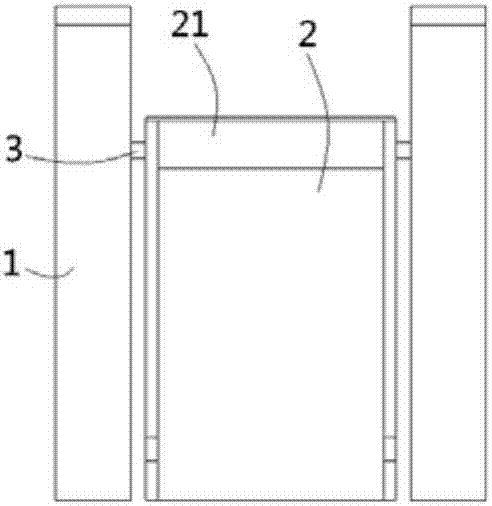
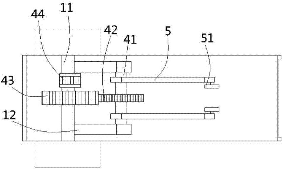
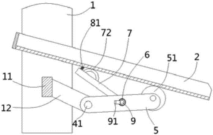
[0021] see figure 1 , figure 2 According to the present invention, a waste material discharge mechanism with a variable waste landing site includes a column 1 on a punching machine, and an oblique discharge trough plate 2 is arranged between the column 1, and the discharge trough plate 2 A baffle 21 is fixed on the upper end surface, and a pillar 3 is plugged and fixed on the upper end of the discharge trough plate 2, and the two ends of the pillar 3 are inserted on the column 1, and a A crossbeam 11, the two sides of the crossbeam 11 are formed with inclined support plates 12, and a rotating shaft 41 is hinged between the support plates 12, and a driven gear 42 is fixe...


PUM


Abstract

The invention discloses a waste landing point-variable waste discharge mechanism. The waste landing point-variable waste discharge mechanism comprises stand columns on a punching machine; an inclineddischarge groove plate is arranged between the stand columns; a rotating shaft is hinged between the stand columns; support rods are fixedly inserted in the two sides of the rotating shaft; one ends of the support rods butt against the bottom surface of the discharge groove plate; a support shaft is inserted between the support rods; beating rods are inserted in the two sides of the support shaft,and are provided with arc beating plates; pressure springs are fixed on the beating rods on one sides above the beating plates; one end of the support shaft penetrates through the support rods, and is inserted with a torsion spring; the two ends of the torsion spring are respectively fixed on the side walls of the support rods and the support shaft; a limiting rod is inserted in the end side wallof the support shaft, and cooperates with a spline of the support shaft; limiting keys are molded on the side wall of the limiting rod; limiting grooves are molded on the side walls of the support rods; and the limiting keys are inserted in the limiting grooves. The waste landing point-variable waste discharge mechanism is variable in waste landing point, is suitable for loading wastes in large waste frames, and meanwhile, can realize smooth discharge of wastes.

Description

Technical field: [0001] The invention relates to the technical field of moulds, in particular to a waste discharge mechanism with a variable waste landing point. Background technique: [0002] In the process of die stamping products, after the material is stamped by the punch and die, waste will be cut out, which needs to be cleaned up in time. In the existing mold manufacturing equipment, there is a planar waste material slide-out groove located under the mold, which is used to accept the generated waste material. The waste material falls into the waste material slide-out groove and then slides out along the waste material discharge groove. Whether the waste material can be smoothly Sliding out of the waste discharge chute directly affects subsequent work. The bottom of the existing waste discharge tank is a plane, and the waste is prone to local accumulation in the plane discharge tank, resulting in poor sliding of the waste, and at the same time, the landing points of th...

Claims


Application Information

Patent Timeline
IPC IPC(8): B21D45/00B21D22/02
CPCB21D22/02B21D45/00
Inventor 杨勇
Owner 金鹏飞
Why Eureka
Try Eureka