
Hydraulic jack

A technology of hydraulic jacks and hydraulic cylinders, applied in the field of hydraulic jacks, can solve the problems of limited lifting height, low stability of the jack, laborious use, etc., and achieve the effects of increased lifting height, difficult to lift off, and large area

Inactive Publication Date: 2018-04-27
WUHAN UNIV OF SCI & TECH
View PDF7 Cites 3 Cited by
  • Summary
  • Abstract
  • Description
  • Claims
  • Application Information

AI Technical Summary

Problems solved by technology

[0004] The invention provides a hydraulic jack, which solves or partially solves the technical problems in the prior art that the jack is not stable when it is working, the lifting height is limited, and it is laborious to use.

Method used


Image

  • Hydraulic jack

Examples


Embodiment Construction

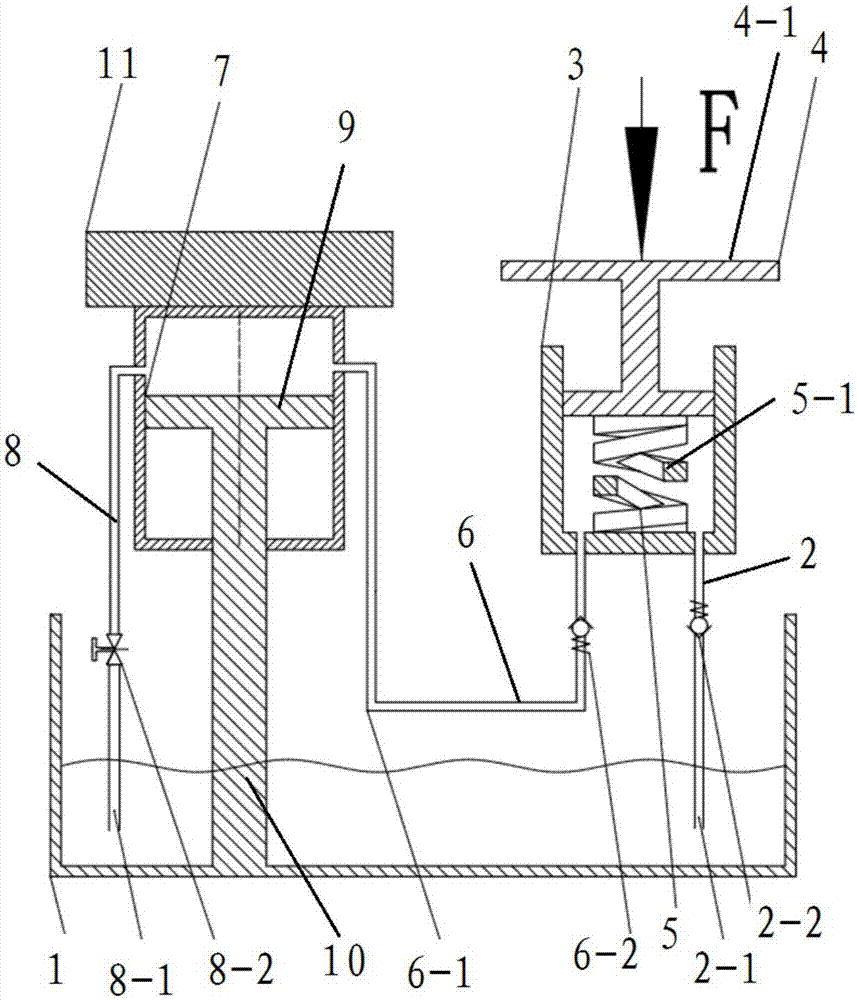
[0017] see figure 1 , a hydraulic jack provided by an embodiment of the present invention includes: a fuel tank 1, a first conveying device 2, an auxiliary hydraulic cylinder 3, a pressing device 4, a restoring device 5, a second conveying device 6, a main hydraulic cylinder 7, a third conveying Device 8, piston rod 10 and piston 9.

[0018] The first end of the first conveying device 2 communicates with the oil tank 1 , and the second end communicates with the rodless cavity of the auxiliary hydraulic cylinder 3 .

[0019] The pressing device 4 is movably arranged in the auxiliary hydraulic cylinder 3 .

[0020] The return device 5 is arranged in the auxiliary hydraulic cylinder 3 , and the return device 5 is arranged between the pressing device 4 and the first end of the auxiliary hydraulic cylinder 3 .

[0021] The first end of the second conveying device 6 communicates with the rodless chamber of the auxiliary hydraulic cylinder 3 , and the second end communicates with t...


PUM


Abstract

The invention discloses a hydraulic jack, and belongs to the technical field of hoisting equipment. The hydraulic jack comprises an oil tank, a first conveying device, a press-down device, a return device, a second conveying device, a third conveying device, a piston rod and a piston. The first end of the first conveying device communicates with the oil tank, and the second end of the first conveying device communicates with a rodless cavity of an auxiliary hydraulic cylinder. The press-down device is movably arranged in the auxiliary hydraulic cylinder. The return device is arranged in the auxiliary hydraulic cylinder and arranged between the press-down device and the first end of the auxiliary hydraulic cylinder. The first end of the second conveying device communicates with the rodlesscavity of the auxiliary hydraulic cylinder, and the second end of the second conveying device communicates with a rodless cavity of a main hydraulic cylinder. The first end of the third conveying device communicates with the rodless cavity of the main hydraulic cylinder, and the second end of the third conveying device communicates with the oil tank. The first end of the piston rod is arranged inthe oil tank, and the second end of the piston rod is movably arranged in the main hydraulic cylinder. The piston is arranged at the second end of the piston rod. By means of the hydraulic jack, a hydraulic cylinder barrel can stretch out and contract, the output force of the jack can be improved, space can be saved, and the hoisting height of the jack can be increased.

Description

technical field [0001] The invention relates to the technical field of lifting equipment, in particular to a hydraulic jack. Background technique [0002] Jack is the simplest lifting equipment that a kind of lifting height is little. It has two kinds of mechanical and hydraulic. There are two types of mechanical jacks, the rack type and the screw type. Due to the small lifting capacity and laborious operation, they are generally only used for mechanical maintenance work, and are not suitable for bridge repairing. Hydraulic jacks are widely used because of their compact structure, stable operation and self-locking effect. Its disadvantage is that the lifting height is limited and the lifting speed is slow. [0003] The jack in the prior art is fixed by the cylinder, and the piston is stretched out under the action of the hydraulic oil to lift the heavy object; in addition, the pressure building mostly adopts the principle of the lever, and the lever is pressed and lifted ...

Claims


Application Information

Patent Timeline
Patent Type & Authority Applications(China)
IPC IPC(8): B66F3/26B66F3/42
CPCB66F3/26B66F3/42
Inventor 郑华生朱学彪崔刚李扬
Owner WUHAN UNIV OF SCI & TECH
Learn More