Check patentability & draft patents in minutes with Patsnap Eureka AI!

Depolarization system and depolarization method for polarized light

A polarized light and depolarization technology, which is applied in the field of quantum phase encoding, can solve the problems of increasing the complexity of device processing and increasing the number of polarization-maintaining fibers, and achieve the effects of saving polarization-maintaining fibers, reducing complexity, and reducing production costs

Pending Publication Date: 2018-04-27
ZHEJIANG QUANTUM TECH CO LTD
View PDF1 Cites 0 Cited by
  • Summary
  • Abstract
  • Description
  • Claims
  • Application Information

AI Technical Summary

Problems solved by technology

[0004] The purpose of the present invention is to provide a depolarization system and depolarization method for polarized light, so as to solve the problem that the depolarizer adopts a three-level device for depolarization, which leads to an increase in the number of polarization-maintaining fibers in the system; the second-level light energy distribution device And when the third polarization beam combiner is fused through their respective polarization-maintaining fibers, the fiber fusion points need to be aligned at an angle of 45°, which increases the technical problems of device processing complexity.

Method used


Image

  • Depolarization system and depolarization method for polarized light
  • Depolarization system and depolarization method for polarized light
  • Depolarization system and depolarization method for polarized light

Examples


Embodiment Construction

[0023] The present invention will be clearly and completely described below with reference to the accompanying drawings in the embodiments of the present invention.

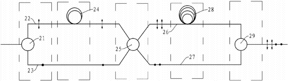
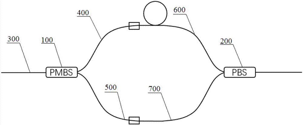
[0024] like figure 1 As shown, a depolarization system for polarized light includes a front-end polarization-maintaining beam splitter 100 and a rear-end polarization beam splitter 200. The polarization-maintaining beam splitter 100 splits the beam with 3dB energy, which can split the incident The light of the polarization maintaining beam splitter 100 is divided into two beams of outgoing light with equal intensity and the same polarization state. Polarization maintaining optical fiber 400, the third polarization maintaining optical fiber 500, the incident end of described polarization beam splitter 200 is respectively connected with the fourth polarization maintaining optical fiber 600 and the fifth polarization maintaining optical fiber 700, the outgoing end of described polarization beam splitter 200 is conne...


PUM


Abstract

The invention provides a depolarization system for polarized light. A 3 dB energy splitting polarization-maintaining beam splitter is used. The incidence end of the polarization-maintaining beam splitter is connected with a first polarization-maintaining optical fiber. The exit end of the polarization-maintaining beam splitter is connected with a second polarization-maintaining optical fiber and athird polarization-maintaining optical fiber. The incidence end of a polarization beam splitter is connected with a fourth polarization-maintaining optical fiber and a fifth polarization-maintainingoptical fiber. The second polarization-maintaining optical fiber and the fourth polarization-maintaining optical fiber are connected to form a long arm. The third polarization-maintaining optical fiber and the fifth polarization-maintaining optical fiber are connected to form a short arm. The arm length difference between the long arm and the short arm is greater than the generation distance of the transmission light coherence time. Compared with the prior art, the depolarization system provided by the invention has the advantages that the depolarization system consists of the polarization-maintaining beam splitter and the polarization beam splitter; the fusion point of optical fibers between two devices does not need to deflect a 45-degree countershaft, but uses a 0-degree countershaft; two devices are connected through an optical fiber; and in addition, the depolarization system adopts two-stage devices in lap joint, which saves a large amount of polarization-maintaining optical fibers, reduces the complexity of the system, and reduces the production cost.

Description

technical field [0001] The invention relates to the technical field of quantum phase encoding, in particular to a depolarization system and a depolarization method for polarized light. Background technique [0002] Depolarization technology is an effective method to eliminate polarization-related effects in single-mode optical fiber application systems. It plays an important role in long-distance optical fiber communication, coherent sensing and measurement systems. With the development of network communication, the data transmission of optical fiber network Speeds are getting faster and higher, so are the capacity requirements for fiber optic networks. Most of the existing optical fiber networks transmit polarized light, and the resulting polarization-dependent loss, polarization-dependent gain and other interferences sensitive to polarized light affect the quality of optical fiber network transmission signals. Therefore, some existing optical fiber networks use optical de...

Claims


Application Information

Patent Timeline
IPC IPC(8): G02B6/27
CPCG02B6/2706G02B6/276G02B6/2773G02B6/2786
Inventor 宋萧天曹文钊赵义博
Owner ZHEJIANG QUANTUM TECH CO LTD
Features
  • R&D
  • Intellectual Property
  • Life Sciences
  • Materials
  • Tech Scout
  • Unparalleled Data Quality
  • Higher Quality Content
  • 60% Fewer Hallucinations
Learn More