
Antitheft electric power cabinet convenient for moving and fixing

A technology for moving and fixing power cabinets, applied in the field of electric power, can solve problems such as affecting the normal use of power equipment, inconvenient and stable placement of power cabinets, and complex internal environment of the cabinet, so as to improve the anti-theft ability, good drying effect, and low maintenance costs. Effect

Inactive Publication Date: 2018-04-27
李秋平
View PDF0 Cites 4 Cited by
  • Summary
  • Abstract
  • Description
  • Claims
  • Application Information

AI Technical Summary

Problems solved by technology

[0002] In the field of power infrastructure, power cabinets are common equipment. The current power cabinets are mainly composed of a roughly rectangular metal shell; when many power cabinets are used outdoors, due to the complex ground environment, it is often difficult to place the power cabinets stably The problem is that the power cabinet is heavy and inconvenient to move. Because the power components work to release magnetic fields and voltages, the internal environment of the cabinet is relatively complicated. There are static electricity and magnetic fields. With the change of air pressure and humidity, the internal static electricity and magnetic fields are all in Changes, how to reasonably control the internal environment to make it suitable for the work of power components and related control equipment has always been a problem for power cabinets. Some power equipment cannot work normally under low temperature conditions, which affects the normal use of power equipment; therefore, we need A kind of anti-theft power cabinet which is convenient to move and fix

Method used


Image

  • Antitheft electric power cabinet convenient for moving and fixing
  • Antitheft electric power cabinet convenient for moving and fixing
  • Antitheft electric power cabinet convenient for moving and fixing

Examples


Embodiment Construction

[0015] The technical solution of this patent will be further described in detail below in conjunction with specific embodiments.

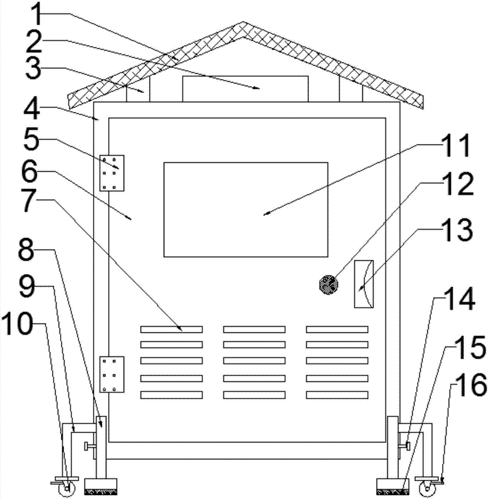
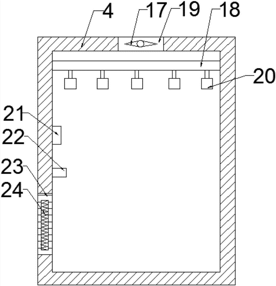
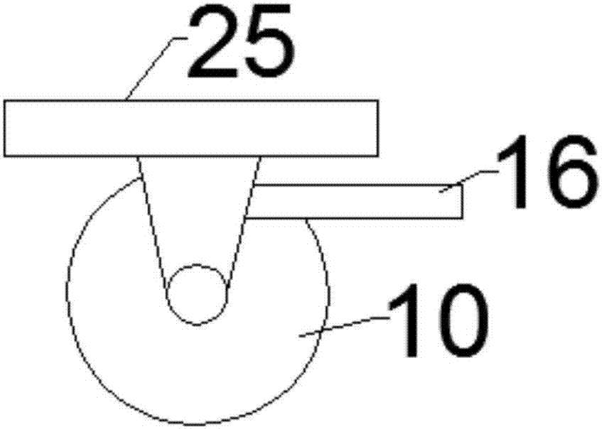
[0016] see Figure 1-3 , a mobile and fixed anti-theft power cabinet, including a power cabinet device and a mobile fixing device; the power cabinet device includes a solar panel 1, a storage battery 2, a support frame 3, a cabinet body 4, a hinge 5, a cabinet door 6, and a cooling grid Grid 7, observation window 11, fingerprint lock 12, cabinet door handle 13, cooling fan 17, cross bar 18, air outlet 19, drying bag 20, temperature sensor 21, controller 22, air inlet 23 and resistance wire 24; The solar battery panel 1 is fixedly arranged on the top of the cabinet body 4 through the support frame 3, and the support frame 3 is fixedly arranged above the outer side of the cabinet body 4; the battery 2 is fixedly arranged above the cabinet body 4, and the battery 2 and the solar battery panel 1 are electrically connected The left end of the cabinet d...


PUM


Abstract

The invention discloses a mobile and fixed anti-theft power cabinet, which includes a power cabinet device and a mobile fixing device; the left end of the cabinet door is arranged on the front side of the cabinet body through two upper and lower hinges, and an observation window is arranged on the upper side of the cabinet door. The lower side of the cabinet door is provided with a heat dissipation grill; the horizontal bar is arranged on the upper side of the cabinet body, and the left and right ends of the bar are fixed on the inner walls of the left and right sides of the cabinet body. Several drying bags are evenly arranged on the bar. Anhydrous calcium chloride desiccant is provided; a temperature sensor and a controller are set up and down in the middle section of the inner wall on the left side of the cabinet, an air inlet is provided on the lower left side of the cabinet, a resistance wire is provided inside the air inlet, and a The air outlet is equipped with a cooling fan; the invention is an anti-theft power cabinet that is easy to move and fix, and has a reasonable structural design and a long service life. , low maintenance cost and strong practicability.

Description

technical field [0001] The invention relates to the field of electric power, in particular to a mobile and fixed anti-theft power cabinet. Background technique [0002] In the field of power infrastructure, power cabinets are common equipment. The current power cabinets are mainly composed of a roughly rectangular metal shell; when many power cabinets are used outdoors, due to the complex ground environment, it is often difficult to place the power cabinets stably The problem is that the power cabinet is heavy and inconvenient to move. Because the power components work to release magnetic fields and voltages, the internal environment of the cabinet is relatively complicated. There are static electricity and magnetic fields. With the change of air pressure and humidity, the internal static electricity and magnetic fields are all in Changes, how to reasonably control the internal environment to make it suitable for the work of power components and related control equipment has...

Claims


Application Information

Patent Timeline
IPC IPC(8): H02B1/30H02B1/56H02B1/28
CPCH02B1/303H02B1/28H02B1/565
Inventor 李秋平
Owner 李秋平
Learn More