Signal demodulation system

A signal demodulation and control module technology, applied in transmission systems, electromagnetic wave transmission systems, electromagnetic receivers, etc., can solve the problems of complex system structure and high design cost, and achieve the effect of simple system operation, short development cycle and intuitive interface

Inactive Publication Date: 2018-04-27
SHAANXI EYOUNG TECH
View PDF0 Cites 0 Cited by
  • Summary
  • Abstract
  • Description
  • Claims
  • Application Information

AI Technical Summary

Problems solved by technology

At present, the lock-in amplifier is mainly used to demodulate the weak signal. The lock-in amplifier mainly uses FPGA, DSP, ARM, etc. as the core control un

Method used


Image

  • Signal demodulation system

Examples


Embodiment 1

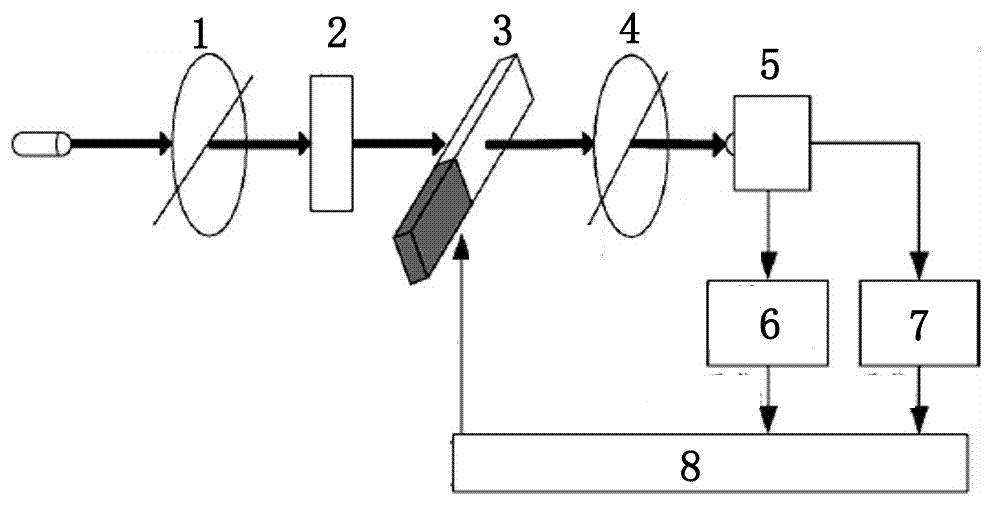
[0013] A signal demodulation system according to the present invention includes a polarizer 1, an optical rotator 2, an optical elastic crystal 3, a polarizer 4, a photodetector 5, a preamplifier 6, a low-pass filter 7, and a control module 8 , wherein the polarizer 1, the optical rotation 2, the elastic crystal 3, the analyzer 4 and the photodetector 5 are connected in sequence, the preamplifier 6 and the low-pass filter 7 are connected to the output end of the photodetector 5, the preamplifier Both the outputs of the amplifier 6 and the low-pass filter 7 are connected to the control module 8 . The control module 8 described in this embodiment is an FPGA control module 8 . The angle of the polarizer 1 in this embodiment is 0 degree in the axial direction. The angle of the analyzer 4 in this embodiment is 45 degrees in the axial direction. One end of the elastic crystal 3 in this embodiment is provided with a piezoelectric quartz, and the output end of the control module 8 i...


PUM


Abstract

The invention relates to a signal demodulation system, which includes a polarizer, an optical rotator, an optical crystal, a polarizer, a photodetector, a preamplifier, a low-pass filter, and a control module. The optical crystal, the polarizer and the photodetector are connected in sequence, and the preamplifier and the low-pass filter are connected to the output end of the photodetector. The signal demodulation system of the present invention can meet the high stability optical rotation data processing requirements, and the system has simple operation, intuitive interface, short development cycle, low cost, industrial production and use, and strong practicability.

Description

technical field [0001] The invention relates to a signal demodulation system. Background technique [0002] The phenomenon that the vibration plane rotates when linearly polarized light passes through some birefringent crystals is called the optical rotation phenomenon. By measuring the optical rotation angle, the analysis of the purity, concentration, structure and composition of the sample can be realized. At present, the measurement of polarimetry is mostly realized by polarimeters, such as the SGW-1 automatic polarimeter of Shanghai Jingke, the IP120-digi4 digital platform polarimeter of Shanghai Yimai, and the 341 / 343 automatic precision polarimeter of PerkinElmer in the United States. It can meet the general application fields that do not require high precision. In 2015, we first proposed a high-precision optical rotation angle measurement method based on elasto-optic modulation PEM, which has the advantages of high sensitivity, high precision, and good stability. At...

Claims


Application Information

Patent Timeline
IPC IPC(8): H04B10/69
CPCH04B10/69H04B10/691
Inventor 张俊
Owner SHAANXI EYOUNG TECH
Why Eureka
Try Eureka