Film covering device and film covering method thereof

A technology of film covering device and film device, which is applied in the direction of packaging material feeding device, packaging, transportation packaging, etc., which can solve the problem of small production volume demanders who are not attractive, non-planar products that cannot be filmed, and low production efficiency, etc. problems, to achieve the effects of reducing labor costs, improving film covering efficiency, and improving production efficiency

Active Publication Date: 2019-10-18
温州市创新晶彩科技有限公司
View PDF5 Cites 2 Cited by
  • Summary
  • Abstract
  • Description
  • Claims
  • Application Information

AI Technical Summary

Problems solved by technology

[0004] (1) Manual lamination, this film lamination method has low efficiency, poor effect and large manpower demand;
[0005] (2) Use automatic film lamination machines on the market for lamination, but most of the existing automatic film lamination machines have complex structures, and can only carry out film lamination in one direction, and cannot apply film to non-planar products, so the applicability is poor
[0007] With the development of printing technology, more and more enterprises, schools and even families have begun to use laminating devices, but at the same time they generally produce less when they use them, and the existing laminating devices are relatively large in size and expensive to purchase. The cost is high, and it is not very attractive to the demanders of small production volumes, and the existing lamination devices generally can only laminate on one side. If double-sided lamination is required, a second lamination is required instead of one Double-sided lamination, which also leads to lower production efficiency

Method used


Image

  • Film covering device and film covering method thereof
  • Film covering device and film covering method thereof
  • Film covering device and film covering method thereof

Examples


Embodiment 1

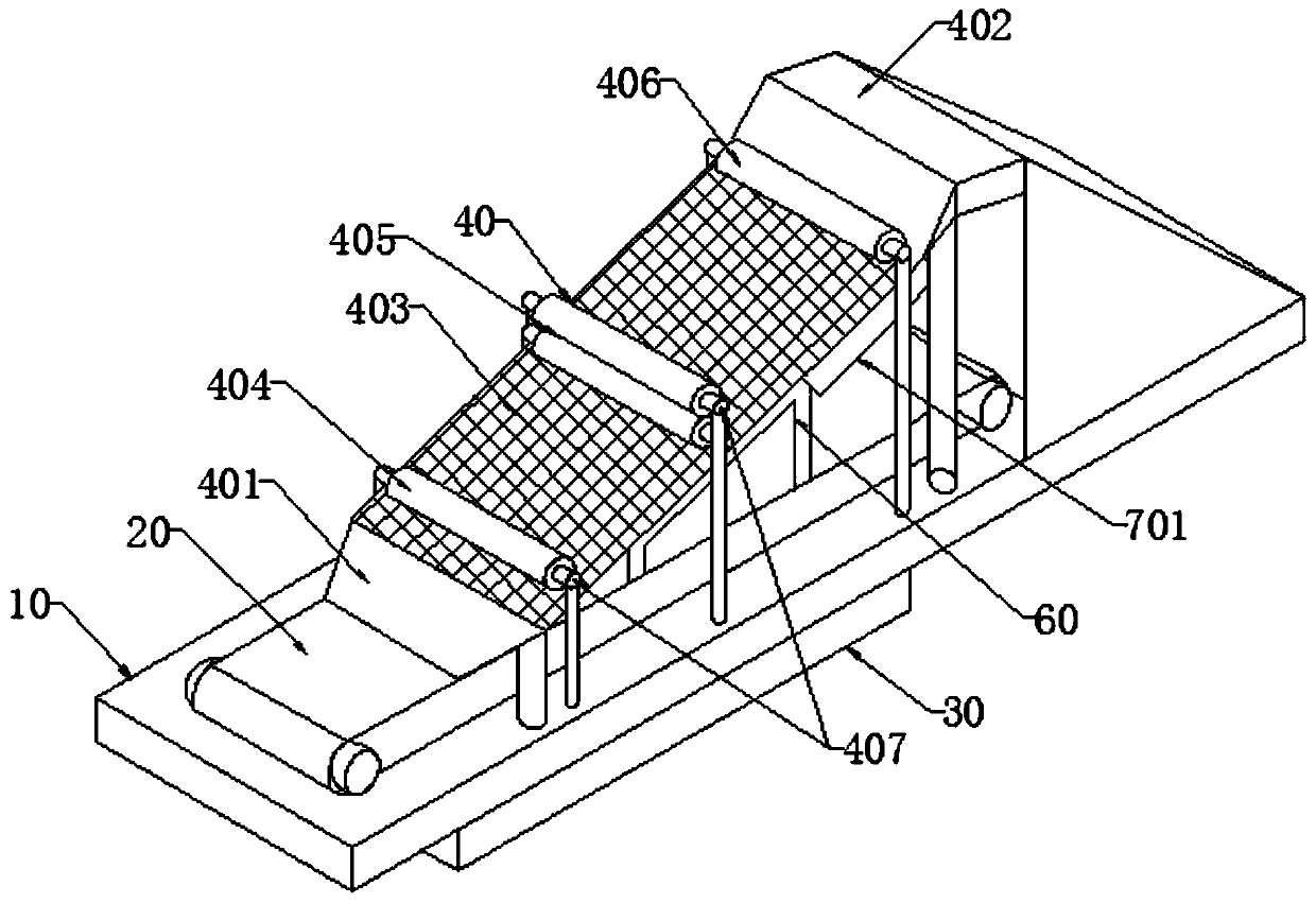
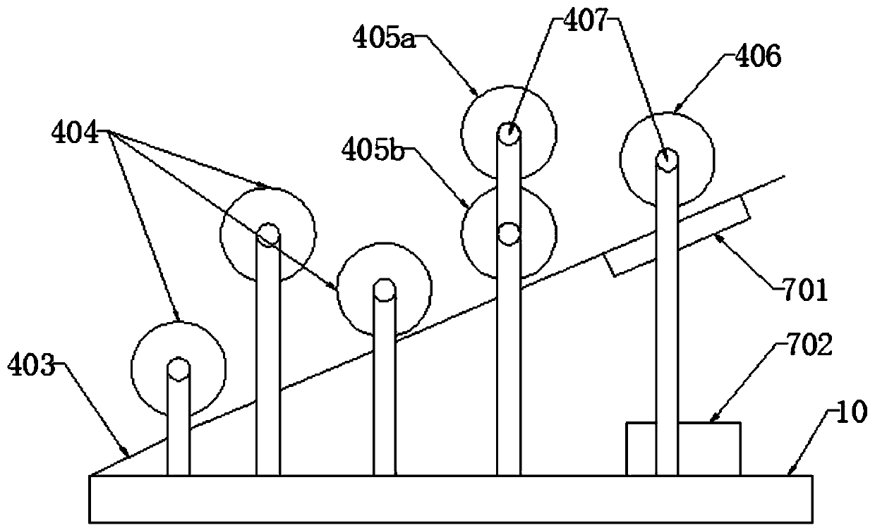
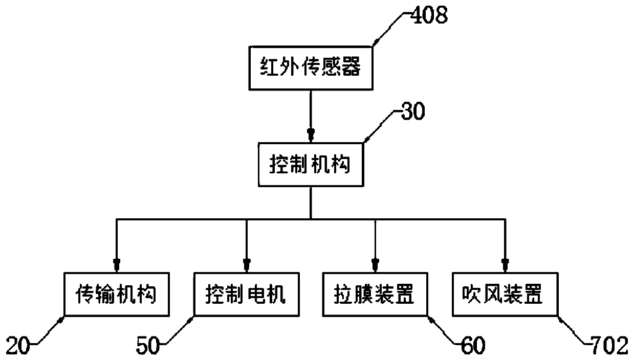
[0042] Such as Figure 1-Figure 3 As shown, a coating device includes a base 10, a transmission mechanism 20, a control mechanism 30 and a coating mechanism 40, the control mechanism 30 is arranged below the base 10, and the transmission mechanism 20 is installed above the base 10 On the surface, the film covering mechanism 40 is arranged above the transmission mechanism 20, and the transmission mechanism 20 runs through the film covering mechanism 40. The film covering mechanism 40 includes a feed port 401, a discharge port 402, a film release plate 403, a flattening roller 404, Laminating roll 405 and auxiliary cooling roll 406, described film release plate 403 has an upward inclination angle of 45°, flattening roll 404, film coating roll 405 and auxiliary cooling roll 406 are located above the film release plate 403 successively, and are close to the film release plate Diaphragm 403; the transmission mechanism 20 moves along the direction of the feed port 401, the feed port...

Embodiment 2

[0044] A film covering device, comprising a base 10, a transmission mechanism 20, a control mechanism 30 and a film covering mechanism 40, the control mechanism 30 is arranged below the base 10, the transmission mechanism 20 is installed on the upper surface of the base 10, the The film covering mechanism 40 is arranged above the transmission mechanism 20, and the transmission mechanism 20 runs through the film covering mechanism 40. The film covering mechanism 40 includes a feed port 401, a discharge port 402, a film release plate 403, a flattening roller 404, and a film covering roller. 405 and auxiliary cooling roller 406, the film releasing plate 403 has an upward inclination of 60°, the flattening roller 404, the laminating roller 405 and the auxiliary cooling roller 406 are sequentially located above the film releasing plate 403, and are close to the film releasing plate 403 The transmission mechanism 20 moves along the feed port 401 direction, the feed port 401 connects ...

Embodiment 3

[0046] A film covering device, comprising a base 10, a transmission mechanism 20, a control mechanism 30 and a film covering mechanism 40, the control mechanism 30 is arranged below the base 10, the transmission mechanism 20 is installed on the upper surface of the base 10, the The film covering mechanism 40 is arranged above the transmission mechanism 20, and the transmission mechanism 20 runs through the film covering mechanism 40. The film covering mechanism 40 includes a feed port 401, a discharge port 402, a film release plate 403, a flattening roller 404, and a film covering roller. 405 and auxiliary cooling roller 406, the film release plate 403 has an upward inclination angle of 50 °, the flattening roller 404, the film roll 405 and the auxiliary cooling roll 406 are located above the film release plate 403 in turn, and are close to the film release plate 403 The transmission mechanism 20 moves along the feed port 401 direction, the feed port 401 connects the entrance o...


PUM

PropertyMeasurementUnit
diameteraaaaaaaaaa

Abstract

The invention discloses a film coating device which comprises a base, a transmission mechanism arranged above the base, a control mechanism arranged below the base and a film coating mechanism arranged above the transmission mechanism, wherein the film coating mechanism comprises a feeding hole, a discharging hole, a film placement plate, a planishing roller, a film coating roller and an auxiliarycooling roller; the film placement plate is positioned between the feeding hole and the discharging hole and has an upward dip angle of 45-60 degrees; the planishing roller, the film coating roller and the auxiliary cooling roller are sequentially positioned above the film placement plate; two transmission rollers are arranged on two sides of each of the planishing roller, the film coating rollerand the auxiliary cooling roller; the transmission rollers are externally connected with a control motor; and the control mechanism controls and is connected with the transmission mechanism and the control motor. The invention further discloses a film coating method of the film coating device. The film coating device can realize automatic film coating to reduce the labor cost, can adjust the filmcoating direction and time, tightens the coated film, realizes a stagger planishing process to enable the films to be level and smooth enough and unified in structure and meet various production demands and improves the production efficiency and the film coating quality.

Description

technical field [0001] The invention relates to the field of film covering, in particular to a film covering device and a film covering method thereof. Background technique [0002] In order to avoid scratches and other problems during the transportation of the product, it is usually necessary to paste a protective film on the surface of the product after the product is produced and before packaging; the film coating device is a special equipment for paper and film. The ready-to-coat laminating device includes three parts: gluing, drying, and hot pressing. It has a wide range of applications and stable and reliable processing performance. It is currently the most widely used laminating equipment in China. [0003] The methods of pasting films commonly used in the prior art include: [0004] (1) Manual lamination, this film lamination method has low efficiency, poor effect and large manpower demand; [0005] (2) Use automatic film lamination machines on the market for lamin...

Claims


Application Information

Patent Timeline
Patent Type & Authority Patents(China)
IPC IPC(8): B65B33/02B65B41/16B65H23/34B65H23/26
Inventor 李娟
Owner 温州市创新晶彩科技有限公司
Why Eureka
Try Eureka