Electromagnetic jaw clutch structure
A claw clutch, clutch technology, applied in the direction of magnetic drive clutch, clutch, non-mechanical drive clutch, etc., can solve the problem of difficult to use passenger car transmission system, and achieve the effect of simple control strategy
- Summary
- Abstract
- Description
- Claims
- Application Information
AI Technical Summary
Problems solved by technology
Method used
Image

Examples
Embodiment 1
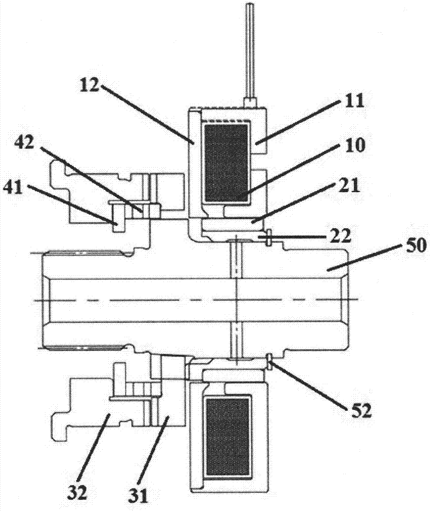
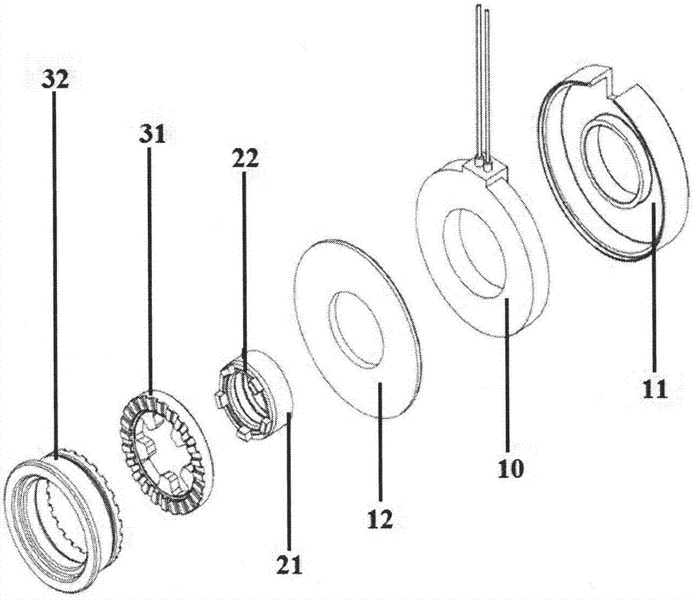
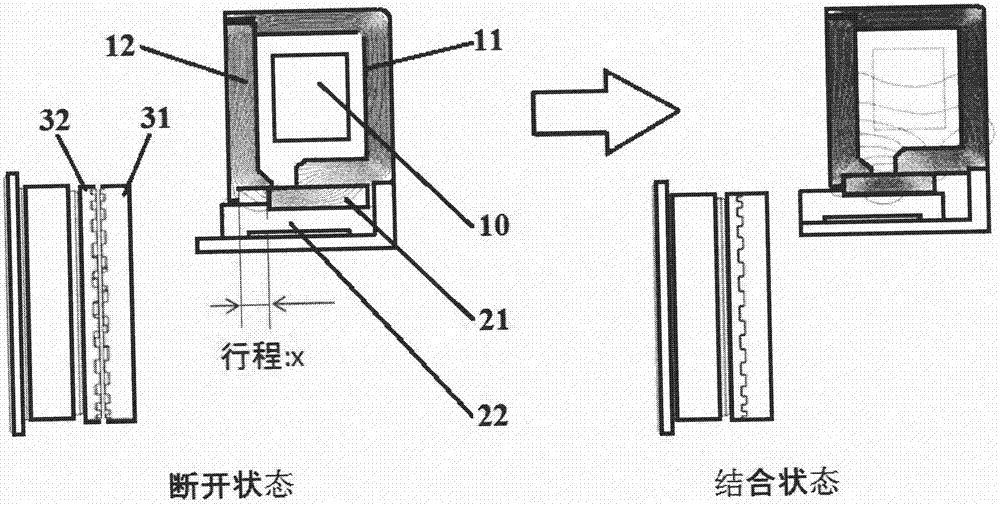
[0029] Such as Figure 1~2 As shown, the structure of the electromagnetic jaw clutch in this embodiment includes a shaft 50 , a coil assembly, a push ring assembly, a clutch driving gear 31 and a clutch passive tooth 32 . The coil assembly includes a main housing 11 , an electromagnetic coil 10 and an end cover 12 . The push ring assembly includes a push ring outer ring 21 and a push ring inner ring 22 fitted in the push ring outer ring 21 . The electromagnetic coil 10 is arranged in the main housing 11 and is closed by an end cap 12 . The coil assembly, the clutch driving gear 31 and the clutch driven gear 32 are sequentially sleeved on the shaft 50 . An annular accommodation space is formed between the coil assembly and the shaft 50 . The push ring assembly is disposed in the annular accommodation space, the push ring assembly is in contact with the inner end of the coil assembly and can move axially relative to the inner end of the coil assembly, and the stroke is X. Th...
PUM
 Abstract
Description
Claims
Application Information
 - Generate Ideas
- Intellectual Property
- Life Sciences
- Materials
- Tech Scout
- Unparalleled Data Quality
- Higher Quality Content
- 60% Fewer Hallucinations
Browse by: Latest US Patents, China's latest patents, Technical Efficacy Thesaurus, Application Domain, Technology Topic, Popular Technical Reports.
© 2025 PatSnap. All rights reserved.Legal|Privacy policy|Modern Slavery Act Transparency Statement|Sitemap|About US| Contact US: help@patsnap.com