Displacement-force compound control lifting system for forging manipulator

A technology for forging manipulators and lifting systems, applied in forging/pressing/hammering machinery, mechanical equipment, manufacturing tools, etc., can solve the problem that the manipulator cannot work efficiently, the lifting force control cannot be achieved, and the proportional pressure valve frequency response Low problems, to achieve the effect of simple structure and control strategy, reduced resistance, and reliable work

Inactive Publication Date: 2011-07-06
ZHEJIANG UNIV
View PDF7 Cites 12 Cited by
  • Summary
  • Abstract
  • Description
  • Claims
  • Application Information

AI Technical Summary

Problems solved by technology

The hoisting system of the currently produced manipulator only has the function of displacement control, and cannot realize the control of the lifting force. However, if the displacement is directly followed by the press control, additional resistance will be generated due to the irregularity of the deformation of the forging. system is very important
[0003] After searching the existing technology, it is found that the Chinese invention patent with the application number of 200810246965.3 discloses a position-pressure control method for the positioning of the hydraulic cylinder of a large forging manipulator, which realizes the displacement-force combination of the manipulator lifting system through a proportional pressure valve Control, the displacement control of this method is realized by force closed loop, which is suitable for working in the working condition of the press forging the workpiece, but it is not suitable for the precise control of the vertical displacement of the workpiece in the non-forging working condition
And the frequency response of the proportional pressure valve is low, resulting in slow system response, which cannot meet the needs of efficient operation of the manipulator

Method used


Image

  • Displacement-force compound control lifting system for forging manipulator
  • Displacement-force compound control lifting system for forging manipulator
  • Displacement-force compound control lifting system for forging manipulator

Examples


Embodiment 1

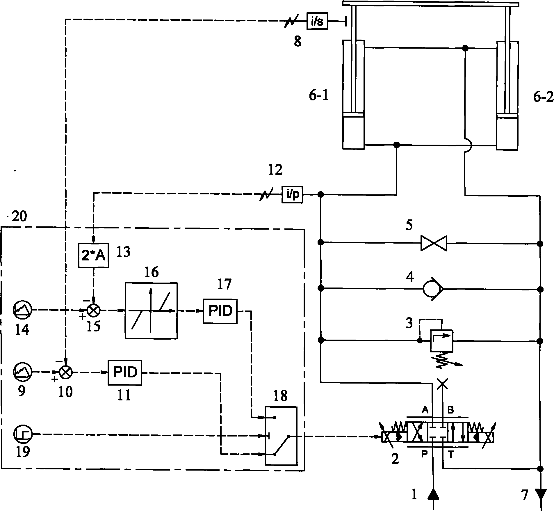
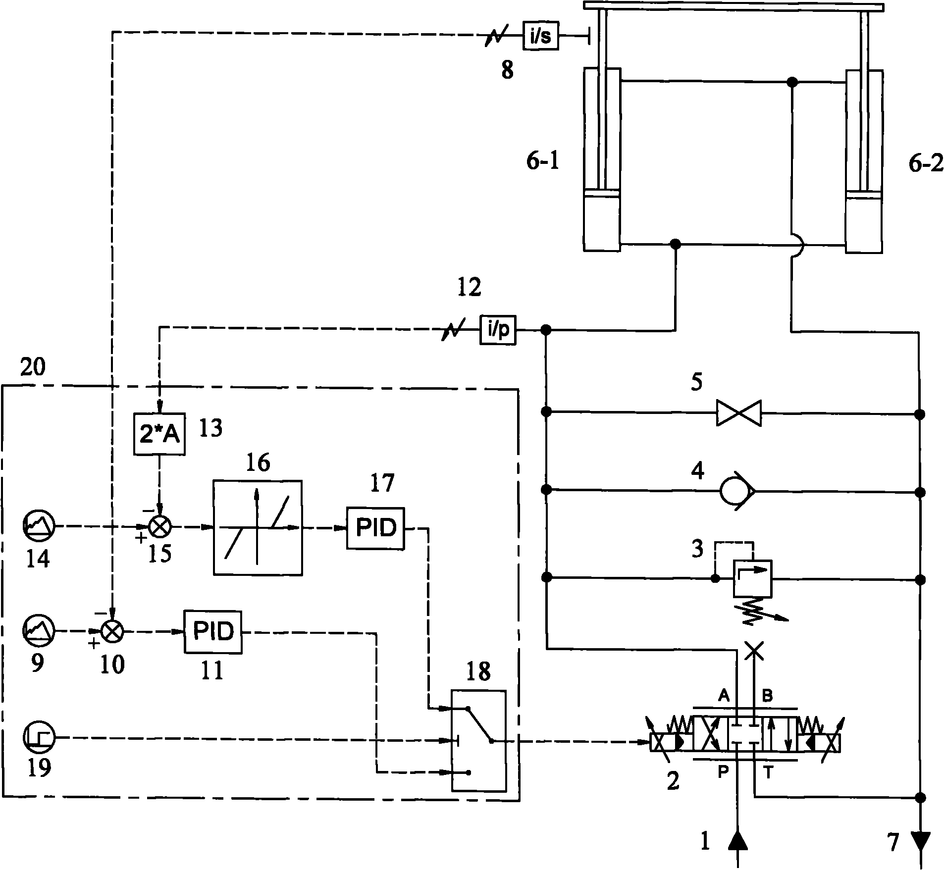
[0018] Embodiment 1. A displacement-force composite control lift system for a forging manipulator, which consists of an oil supply port 1, a proportional servo valve 2, a safety valve 3, a one-way valve 4, a stop valve 5, and a left lift cylinder 6-1 , right lifting cylinder 6-2, oil source and oil return port 7, displacement sensor 8, pressure sensor 12 and displacement-force composite controller 20.

[0019] Port P of proportional servo valve 2 is connected to oil supply port 1 of the oil source; port B of proportional servo valve 2 is sealed; port A of proportional servo valve 2 is connected to the inlet of safety valve 3, the outlet of one-way valve 4, the inlet of stop valve 5, the pressure Sensor 12, left lift cylinder 6-1 lower chamber connected with right lift cylinder 6-2 lower chamber; oil source return port 7 and T port of proportional servo valve 2, safety valve 3 outlet, one-way valve 4 inlet, stop valve 5 outlet, left lifting cylinder 6-1 upper cavity, right lift...


PUM


Abstract

The invention discloses a displacement-force compound control lifting system for a forging manipulator. A port P of a proportional servo valve (2) is connected with an oil supply port (1) of an oil source; a port A of the proportional servo valve (2) is respectively connected with an inlet of a safety valve (3), an outlet of a check valve (4), an inlet of a stop valve (5), a pressure sensor (12) and lower cavities of two lifting cylinders; an oil return port (7) of the oil source is respectively connected with a port T of the proportional servo valve (2), an outlet of the safety valve (3), an inlet of the check valve (4), an outlet of the stop valve (5) and upper cavities of the two lifting cylinders; mechanisms at top ends of piston rods of the two lifting cylinders are fixedly connected; a displacement sensor (8) is internally arranged on the piston rods; and a signal output end of the displacement sensor (8), a signal output end of the pressure sensor (12) and a signal input end of the proportional servo valve (2) are connected with a displacement-force compound controller through signals. Due to the adoption of the system, the response speed can be increased, and the compliance in the vertical direction can be improved.

Description

technical field [0001] The invention relates to an electro-hydraulic proportional lifting system, in particular to a displacement-force compound control lifting system of a forging manipulator. Background technique [0002] The free forging forging manipulator is used to grab the forging workpiece and perform certain actions, and it is used in conjunction with the press to improve the forging efficiency. Generally speaking, the manipulator can realize the vertical, horizontal, front and rear, pitch, side swing and other movements of the forged workpiece. Among them, for the manipulator controlled independently by the front and rear lifting systems, the lifting system controls the vertical lifting of the forged workpiece, and the rear The lifting system or the pitching system controls the pitching motion of the forged workpiece (see Chinese invention patents with application numbers 200810037835.9 and 201010133714.1). When the press forges the workpiece, due to plastic defor...

Claims


Application Information

Patent Timeline
Patent Type & Authority Applications(China)
IPC IPC(8): B21J13/10F15B11/22
Inventor 周华侯交义傅新杨华勇
Owner ZHEJIANG UNIV
Why Eureka
Try Eureka