
Method for designing cross section of corrugated steel plate arch bridge based on optimal stress state

A technology of corrugated steel plate and stress state, which is applied in the direction of computer-aided design, calculation, special data processing application, etc., can solve the problems of increasing section bending moment, increasing vertical settlement of arch bridge, prone to deformation, etc., and achieves reduction Effects of horizontal thrust, reduced steel consumption, and reduced bending moment

Active Publication Date: 2018-05-01
EAST CHINA JIAOTONG UNIVERSITY
View PDF5 Cites 6 Cited by
  • Summary
  • Abstract
  • Description
  • Claims
  • Application Information

AI Technical Summary

Problems solved by technology

[0004] However, despite the presence of corrugations, the section flexural stiffness of corrugated steel plate arch bridges is much smaller than that of reinforced concrete girder bridges. The reason for filling soil or driving directly on the upper part
In addition, when there is a horizontal thrust on the arch foot of the corrugated steel plate arch bridge, it is easy to cause horizontal displacement of the arch foot foundation, and the horizontal displacement of the arch foot foundation leads to a decrease in the horizontal restraint force of the arch foot, thereby increasing the section bending moment, and also The vertical settlement of the arch bridge is increased, which is extremely unfavorable to the overall stress of the arch bridge structure and the stability of the upper filling and road surface
Because of this, the span of the existing corrugated steel plate arch bridge is very limited, and a large number of popularization and application are limited, especially the application in railway projects with high requirements for smoothness of the upper part needs to be very cautious

Method used


Image

  • Method for designing cross section of corrugated steel plate arch bridge based on optimal stress state
  • Method for designing cross section of corrugated steel plate arch bridge based on optimal stress state
  • Method for designing cross section of corrugated steel plate arch bridge based on optimal stress state

Examples


Embodiment

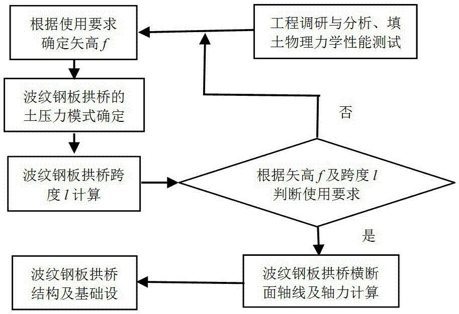
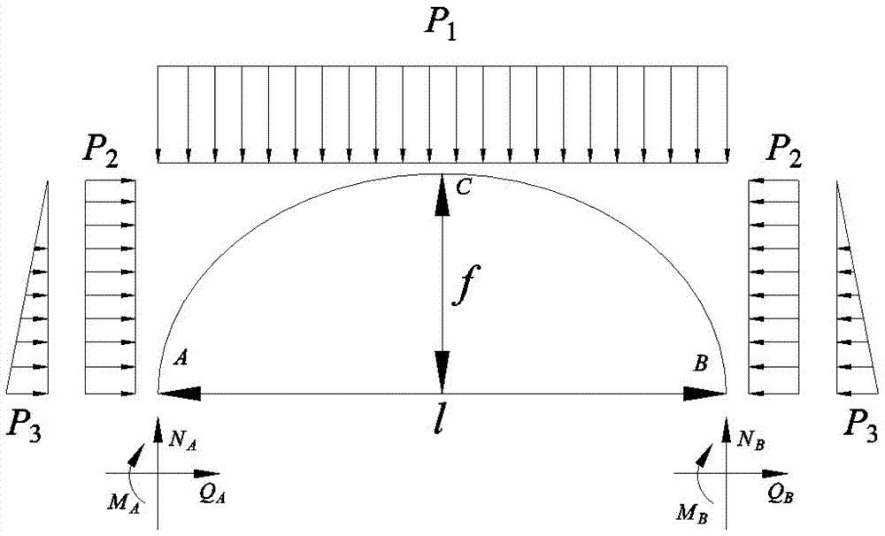
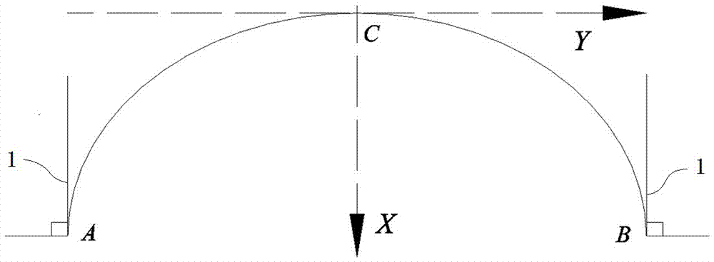
[0064] Example: such as Figure 1-6 As shown, this embodiment specifically relates to a method for designing the cross section of a corrugated steel plate arch bridge based on the optimal stress state. The thickness of the overlying soil and the mechanical properties of the overlying soil, the cross-section axis of the corrugated steel plate arch bridge is vertical at the tangent line 1 at the arch foot position, and the arch foot structure 2 is hinged; the optimal stress state referred to here It means that the theoretical bending moment of the cross section of the corrugated steel plate arch bridge is zero, and the horizontal thrust of the corrugated steel plate arch bridge at the arch foot is also zero; therefore, figure 2 Medium M A =0; M B =0;Q A =0;Q B =0; the cross-section design method of the corrugated steel plate arch bridge specifically includes the following steps:

[0065] (1) Preliminarily determine the sagittal height of the corrugated steel plate arch bri...


PUM


Abstract

The invention discloses a method for designing a cross section of a corrugated steel plate arch bridge based on an optimal stress state. The method comprises the following steps: primarily determininga vector height f of the corrugated steel plate arch bridge according to a use requirement of the corrugated steel plate arch bridge; calculating a span l of the corrugated steel plate arch bridge according to the vector height f of the corrugated steel plate arch bridge the mechanical property parameters and thickness of overlaying soil; judging whether the corrugated steel plate arch bridge meet the use requirement according to the calculated span l and vector height f of the corrugated steel plate arch bridge, and repeatedly carrying out steps until the span l and vector height f of the corrugated steel plate arch bridge meet the use requirement; and calculating the axis of the cross section of the corrugated steel plate arch bridge. Compared with a traditional corrugated steel plate arch bridge, the method has the advantages that the bending moment of a corrugated steel plate can be maximally reduced without increasing the construction cost, and the horizontal thrust of a corrugated steel plate foundation is reduced, so that the deformation of the corrugated steel plate arch bridge is reduced, and the steel consumption of the corrugated steel plate arch bridge can be reduced.

Description

technical field [0001] The invention belongs to the technical field of bridges, and in particular relates to a cross-section design method of a corrugated steel plate arch bridge based on an optimal stress state. Background technique [0002] The arch axis of traditional arch bridges (referring to reinforced concrete arch bridges, stone arch bridges, etc.) usually adopts catenary or parabola. Therefore, the design method of the arch axis of the cross section cannot refer to the design method of the arch axis of the traditional arch bridge. In addition, in order to reduce the load on the structure of the traditional arch bridge, the upper part is no longer filled with soil, so generally there is only vertical load on the arch ring; in order to reduce the bending moment on the arch ring, the arch foot must provide horizontal restraint. However, the upper part of the corrugated steel plate arch bridge is filled with soil. Due to the lateral soil pressure generated by the soil,...

Claims


Application Information

Patent Timeline
Patent Type & Authority Applications(China)
IPC IPC(8): G06F17/50
CPCG06F30/13G06F2119/06
Inventor 黄大维冯青松罗文俊刘林芽魏慧芬蒋峻楠李文滨万亮兰彬李欣旺
Owner EAST CHINA JIAOTONG UNIVERSITY
Learn More