Eureka AIR delivers breakthrough ideas for toughest innovation challenges, trusted by R&D personnel around the world.

Battery module cell mounting structure

A technology for installing structures and battery modules, which is applied to battery pack parts, structural parts, circuits, etc., can solve the problems of large support frame, variability of support frame, unfavorable battery box assembly, etc., and achieve the effect of fixing

Inactive Publication Date: 2018-05-01
ANHUI OFFNENBACH NEW ENERGY TECH CO LTD
View PDF8 Cites 0 Cited by
  • Summary
  • Abstract
  • Description
  • Claims
  • Application Information

AI Technical Summary

Problems solved by technology

The existing battery modules usually have the following problems: 1. The plastic supporting frame itself is variable, and the battery cells and the supporting frame at the bottom of the battery module are due to the gravity of the upper battery module structure, and the lower battery module The structure of the group is easily deformed, which will lead to disordered contact between the tabs at both ends of the battery cell and the electrode plate, resulting in failure
2. The thick plastic support frame directly makes the weight of the module larger, so that more power is required for loading and use, which consumes a lot of energy
3. The thick plastic support frame is bulky and takes up more space, which is not conducive to its own assembly in the battery box and is not conducive to the assembly of the battery box on the vehicle

Method used


Image

  • Battery module cell mounting structure
  • Battery module cell mounting structure
  • Battery module cell mounting structure

Examples


Embodiment Construction

[0015] combine Figure 1 to Figure 7 , the present invention is further described:

[0016] The following is a detailed introduction to the cell installation structure of the battery module in combination with the entire battery module:

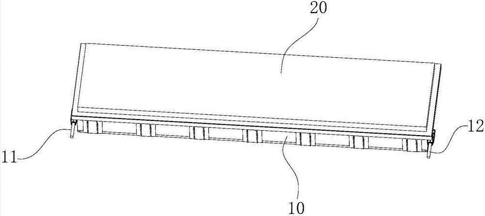
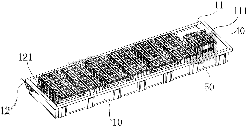
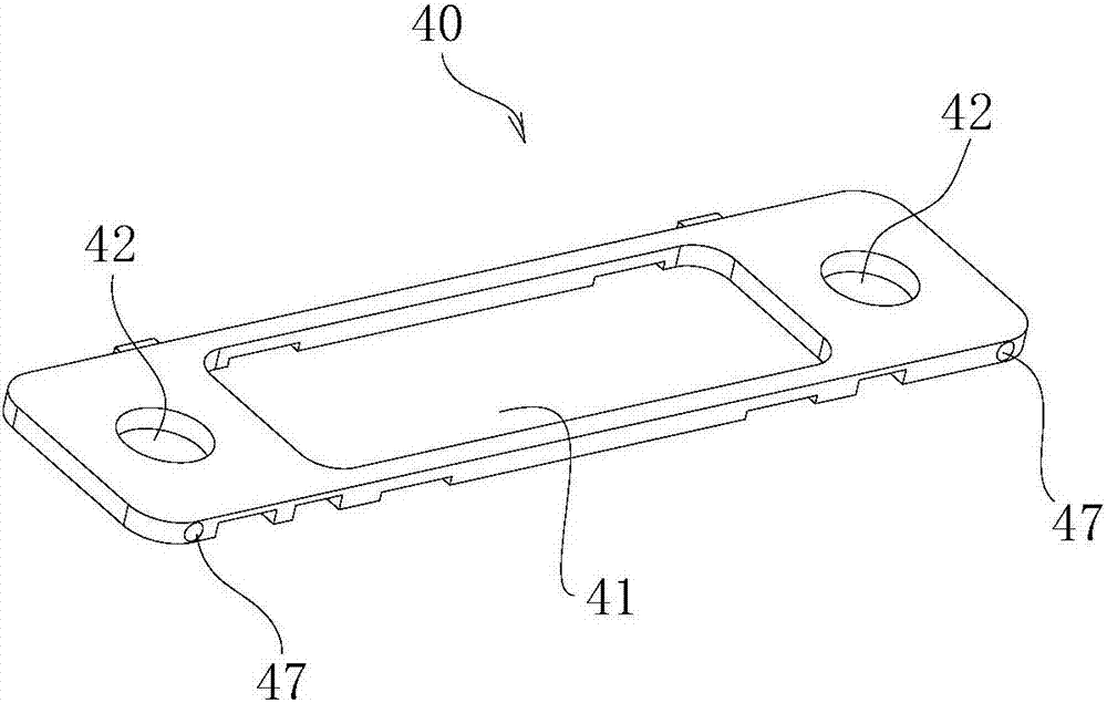
[0017] The battery module includes a bottom bracket 10 for installing the battery module, the bottom bracket 10 has an open box-like structure, the opening of the bottom bracket 10 is provided with a box cover 20, and a plurality of batteries are arranged in the bottom bracket 10 The battery pack is connected in series with each other through the electrical connecting piece 31, and the battery pack is composed of a plurality of battery cells 30, the upper end of the battery cell 30 is provided with a fixing plate 40, and the fixing plates 40 at the upper ends of the adjacent battery cells 30 are spliced ​​together As a whole, the side walls at both ends of the bottom bracket 10 are respectively provided with a negative connection terminal 11...


PUM


Abstract

The invention relates to a battery module cell mounting structure. The structure comprises a base for mounting a battery module, wherein the base is an opened tank structure, a box cover is arranged at an opening of the base, multiple battery packs are arranged in the base, and mutually connected in series through electric connecting sheets; each battery pack is composed of multiple cells, a fixedplate is arranged at the upper end of each cell, the fixed plates at the upper ends of the adjacent cells are mutually spliced into a whole; side walls at two sides of the base are respectively provided with a negative connecting end and a positive connecting end; one end of the mutually and serially connected cells is provided with a positive connecting sheet to connect with the positive connecting end; and the other end of the mutually and serially connected cells is provided with a negative connecting sheet to connect with the negative connecting end; the above battery packs are connectedin series, and the battery packs are mutually connected in series through the electric connecting sheets; the fixed plates at the upper ends of the adjacent cells can be mutually spliced into the whole, therefore, the battery module is light in mass, small in volume, good in insulation in compared with the existing battery module, and can be simply assembled in the battery tank.

Description

technical field [0001] The invention relates to the technical field of power batteries for new energy vehicles, in particular to a battery module cell installation structure. Background technique [0002] Battery modules are the "heart" of electric vehicles. The battery module is the core part of providing power energy for new energy vehicles such as electric vehicles and hybrid vehicles. It can be understood that battery cells are combined in series and parallel, and a battery monitoring and management device (MCN) is installed to manage and control them. The structural design of the battery module can often determine the performance and safety of a battery box. Its structure must support, fix and protect the battery cells. At the same time, how to meet the requirements of overcurrent, current uniformity, how to meet the control of battery cell temperature, and whether to cut off the power when there is a serious abnormality, to avoid chain reactions, etc., will be the c...

Claims


Application Information

Patent Timeline
Patent Type & Authority Applications(China)
IPC IPC(8): H01M2/10H01M50/204
CPCH01M50/20Y02E60/10
Inventor 邵勇
Owner ANHUI OFFNENBACH NEW ENERGY TECH CO LTD
Why Eureka
Eureka Blog
Learn More