Precision actuator with impact-resistant locking device

A locking device and impact-resistant technology, which is applied in the field of precision instruments, can solve the problems of precision, large structure, and non-compliance with Abbe's principle, etc., and achieve the effect of strong impact resistance and reduced control difficulty

Active Publication Date: 2018-05-01
YANSHAN UNIV
View PDF4 Cites 11 Cited by
  • Summary
  • Abstract
  • Description
  • Claims
  • Application Information

AI Technical Summary

Problems solved by technology

Existing technologies cannot effectively solve the problems raised above
Patent 201520118532.5 proposes an LVDT-type to-point actuator, which connects the LVDT displacement sensor to the head of the protruding rod. Since this arrangement does not conform to Abbe’s principle, there is a problem of accuracy, and the The actuator cannot realize the anti-locking impact function and the rotational freedom of the output shaft
Patent 200810219979.6 proposes a precision spindle locking device, which can ensure the precise locking of the spindle, but the impact resistance of the device is not good when locked, and the drive form of the device is hydraulic cylinder drive, and the structure is relatively huge

Method used


Image

  • Precision actuator with impact-resistant locking device
  • Precision actuator with impact-resistant locking device
  • Precision actuator with impact-resistant locking device

Examples


Embodiment 2

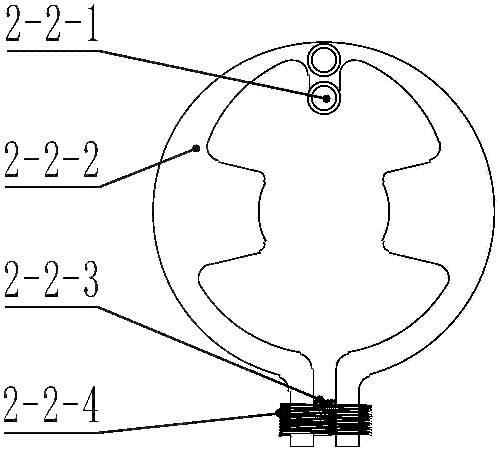
[0036] Such as image 3 As shown, the brake disc 2-2-2 in the anti-shock locking device is a flat ring with an opening, and a fixing pin mounting hole is arranged opposite to the opening, and there are two sides of the brake disc between the opening and the fixing pin mounting hole. Each arm is provided with a protruding inner block with a circular arc surface. The connection between the arms of the brake pad and the mounting hole of the fixing pin is thin-walled. The thin-walled feature can form a flexible rotating pair, that is, block-shaped The body can rotate around the rotation center of the fixed thin-walled feature, and the brake pad is fixedly connected with the surface of the main shell through the fixed pin 2-2-1 arranged in the fixed pin installation hole, and at the same time, the brake pad locking block and the extension rod head The arc surface of the groove is in close contact with the lower surface of the locking groove on the head of the protruding rod. A comp...

Embodiment 3

[0040] Such as Figure 4 with Figure 5 As shown, the locking device housing 2-3-15 in the anti-shock locking device is fixedly connected with the main housing, and one end of the half-moon-shaped clamping lever 2-3-12 in the two locking transmission branches with the same structure passes through the fixed pin shaft 2- 3-13 is connected with the housing of the locking device. There is a mounting groove in the middle of the half-moon clamping lever, and the locking block 2-3-10 with an arc surface inside is placed in the mounting groove and moved by the moving pin 2-3-11 The rotary pair is connected with the half-moon-shaped clamping lever. The inner sides of the two locking blocks are circular arc surfaces and clamped in the groove in the middle of the sliding sleeve. The sliding sleeve 2-3-1 is set on the extension rod, and the extension rod A sliding cylinder pair is formed to guide the extension rod; the other end of the half-moon clamping lever is provided with a U-shape...


PUM


Abstract

A precision actuator with an impact-resistant locking device comprises the impact-resistant locking device, a grating ruler swinging installation block, an extension rod installation head, an extension rod, a driving screw rod, a driving nut, a nut fastening piece, a first motor bearing, a main driving motor, a second motor bearing, a main shell, a motor upper shell and a base. The precision actuator has an impact-resistant locking function, a locking block and the extension rod are locked by a matched groove under a locking state, impact bearing employs a contact form, and the impact-resistant capability can be improved; by employing a fuse mechanism, extra motor control is reduced, and the control difficulty is reduced; and position feedback fully-closed loop is achieved, meanwhile, theextension rod can freely rotate at a small angle, the measurement accuracy cannot be affected, and the actuator is suitably applied to a multi-dimensional gesture adjustment platform.

Description

technical field [0001] The invention belongs to the technical field of precision instruments, in particular to a precision actuator. Background technique [0002] Actuators that realize precise linear motion in a space environment are widely used in space telescopes and space precision pointing mechanisms. For example, the secondary mirror adjustment mechanism of the Hubble Telescope, the attitude adjustment mechanism of the space station’s earth observation camera, etc., all require linear actuators drive. Due to the complexity of the space environment and the need for launch shocks, the requirements for precision actuators used in the space environment are very stringent. For example, the impact acceleration and vibration generated during rocket launch will have a huge impact on precision actuators. If the design structure or strength is unreasonable, it will cause plastic deformation of the actuator's transmission system, which will seriously affect the accuracy. At the...

Claims


Application Information

Patent Timeline
Patent Type & Authority Applications(China)
IPC IPC(8): H02K7/06H02K11/22G02B23/00
Inventor 赵铁石王唱贺星宇丁实兴
Owner YANSHAN UNIV
Why Eureka
Try Eureka