High-sensitivity telephone receiver vibrating diaphragm

A high-sensitivity, receiver technology, applied in the direction of sensors, sensor types, electromechanical sensors, etc., can solve the problems of easy distortion of the receiver, low diaphragm rigidity, unstable connection, etc., and achieve low processing difficulty and large bonding area , the effect of simple structure

Pending Publication Date: 2018-05-01
奥音精密机械(镇江)有限公司
View PDF4 Cites 1 Cited by
  • Summary
  • Abstract
  • Description
  • Claims
  • Application Information

AI Technical Summary

Problems solved by technology

[0003] The principle of the receiver is similar to that of the receiver. They all use the conversion of electricity and magnetism to trigger the vibration and sound part to produce sound. Most of the receivers in use today use the diaphragm and the voice coil as important vibration sound components. Among them, the diaphragm and the voice coil 1. The base body of the receiver is mostly bonded with glue or resin. When connecting, due to the small contact area, the connection is often unstable, and the traditional diaphragm generally has low rigidity and low sensitivity, which makes the prepared receiver easy to be distorted. , and the sound quality is poor

Method used


Image

  • High-sensitivity telephone receiver vibrating diaphragm
  • High-sensitivity telephone receiver vibrating diaphragm

Examples


Embodiment 1

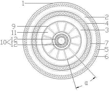
[0018] A high-sensitivity receiver diaphragm as shown in the figure includes a diaphragm main body 1, which is characterized in that the diaphragm main body 1 is circular and includes a fixed part 2 located on the outside, a middle part 3 located in the middle and The connection part 4 between the fixed part 2 and the middle part 3, the fixed part 2, the middle part 3 and the connection part 4 are of an integrated structure;

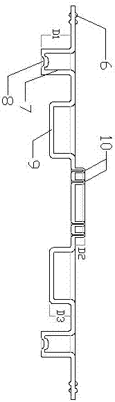
[0019] The fixed portion 2 is circular, and symmetrical fixed regions 5 are arranged on the upper and lower sides of the circular shape, and a plurality of fixed protrusions 6 are arranged in the fixed region 5, and the fixed protrusions The cross-section of 6 is semicircular, and the plurality of fixed protrusions 6 on the same side are arranged at equal intervals, and are evenly distributed in a circular ring. The connecting protrusion 7 is in the shape of a ring, protruding from the upper end surface of the diaphragm main body 1 toward the lower end s...

Embodiment 2

[0026] The diaphragm main body described in Embodiment 1 is a plastic diaphragm, and its material is PET plastic and glass fiber, and its preparation method is as follows:

[0027] (1) Select reinforced PET plastic particles and put them into the melting equipment;

[0028] (2) Continuously evacuate the inside of the melting equipment until the vacuum degree inside the melting equipment is below 100Pa and maintain it. At the same time, start the melting equipment to melt the PET plastic particles;

[0029] (3) After the PET plastic granules are completely melted, add glass fibers that account for 20% of the total mass of the PET plastic granules online, and continue heating with slow stirring at a rate of 30 r / min until the glass fibers are completely melted and combined with the PET plastic Mix evenly to obtain a molten liquid;

[0030] (4) Send the molten liquid obtained in step (3) to MCP three-layer co-extrusion, and stretch it to form a diaphragm sheet;

[0031] (5) The...


PUM


Abstract

The invention provides a high-sensitivity telephone receiver vibrating diaphragm which comprises a vibrating diaphragm body. The vibrating diaphragm body comprises a fixing portion, a middle portion and a connecting portion, a fixing zone with fixing protrusions is arranged on the fixing portion, an annular connecting protrusion is arranged on the connecting portion, a connecting groove is formedin the lower end surface of the connecting protrusion, a primary reinforcement portion and a secondary reinforcement portion are arranged on the connecting portion, the primary reinforcement portion comprises a plurality of fan-shaped primary reinforcement protrusions, and the secondary reinforcement portion comprises a plurality of ring-shaped secondary reinforcement protrusions. The high-sensitivity telephone receiver vibrating diaphragm has the advantages that the high-sensitivity telephone receiver vibrating diaphragm is simple in structure and low in processing difficulty; the adhesion areas can be enlarged by the fixing protrusions on the fixing portion, and the connection strength and the stability further can be improved; the connecting protrusion can be correspondingly connected with a voice coil, the position of the voice coil can be clear at a glance after being connected with the connecting protrusion, accordingly, the adhesion areas can be enlarged, and quality detection can be facilitated; the high-sensitivity telephone receiver vibrating diaphragm is provided with the multistate reinforcement portions, accordingly, the rigidity and the strength of the high-sensitivity telephone receiver vibrating diaphragm can be improved, the area of the high-sensitivity telephone receiver vibrating diaphragm can be increased, internal damping can be enlarged, and distortion canbe reduced; the sensitivity of a telephone receiver can be stabilized, and the voice quality can be guaranteed and improved.

Description

technical field [0001] The invention relates to the field of receiver production, in particular to a high-sensitivity receiver diaphragm. Background technique [0002] The receiver is also called the handset, and the English is Receiver. An electro-acoustic device that converts audio electrical signals into sound signals under the condition of no sound leakage (or 3.2 type high / low leakage ring according to ITU standard), widely used in communication terminal equipment such as mobile phones, landline phones and hearing aids , to achieve audio (speech, music) playback. [0003] The principle of the receiver is similar to that of the receiver. They all use the conversion of electricity and magnetism to trigger the vibration and sound part to produce sound. Most of the receivers in use today use the diaphragm and the voice coil as important vibration sound components. Among them, the diaphragm and the voice coil 1. The base body of the receiver is mostly bonded with glue or r...

Claims


Application Information

Patent Timeline
Patent Type & Authority Applications(China)
IPC IPC(8): H04R7/22H04R7/12
CPCH04R7/127H04R7/22
Inventor 赵俊武尹德斌王路明历成宾乔托米歇尔
Owner 奥音精密机械(镇江)有限公司
Why Eureka
Try Eureka