
Simple acid waste gas purification apparatus

A technology of acid waste gas and purification device, which is applied in the direction of chemical instruments and methods, separation of dispersed particles, separation methods, etc. It can solve the problems of increasing contact area, harsh cleaning environment, and heavy workload, and achieves simple installation, low investment, Configure flexible effects

Inactive Publication Date: 2018-05-04
江西众合装备技术有限公司
View PDF5 Cites 2 Cited by
  • Summary
  • Abstract
  • Description
  • Claims
  • Application Information

AI Technical Summary

Problems solved by technology

[0003] For the treatment of tail gas containing acid mist, only large-scale devices used to have it. Power wave flue gas purification technology is usually used. Packing is placed in the flue or purification tower through which the flue gas passes, and the lye is pumped to the purification tower or pipeline for spraying. Convection with the flue gas, the role of the filler is to increase the contact area, so that the flue gas can contact the lye as much as possible for a chemical neutralization reaction, but most of the neutralized reactants will adhere to the filler, which needs to be cleaned or replaced regularly Packing, the workload is heavy, the cleaning environment is harsh, and production must be stopped during cleaning, and the investment in installing power wave flue gas purification equipment for small devices is too large

Method used


Image

  • Simple acid waste gas purification apparatus
  • Simple acid waste gas purification apparatus

Examples


Embodiment Construction

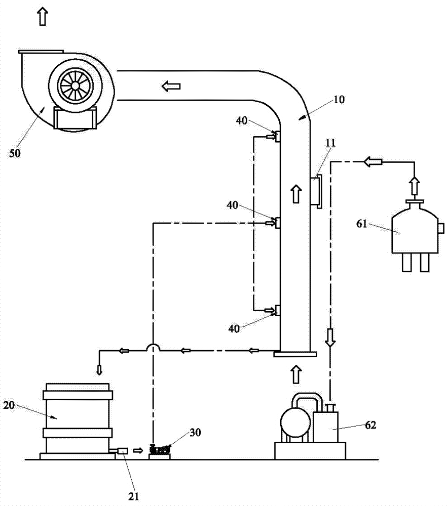
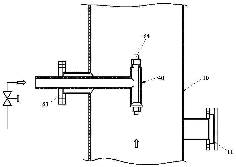
[0024] Please refer to Figure 1 to Figure 2 As shown, it shows the specific structure of the preferred embodiment of the present invention, including the vent pipe 10, the lye storage tank 20, the lye circulation pump 30, the nozzle 40 and the exhaust fan 50.

[0025] The ventilation pipe 10 accepts the waste gas discharged from the system. Specifically, a steam-water separation tank 61 is arranged on the side of the ventilation pipe 10, and the acid waste gas is stored in the steam-water separation tank 61. The acid waste gas in the steam-water separation tank 61 passes through a vacuum pump. 62 is pressed into the ventilation pipe 10;

[0026] The lye storage tank 20 communicates with the lye return port at the lower end of the ventilation pipe 10, and the outlet of the lye storage tank 20 is provided with a valve 41 to control the output of the lye.

[0027] The liquid inlet of the lye circulation pump 30 is connected with the liquid outlet of the lye storage tank 20 , an...


PUM


Abstract

The invention discloses a simple acid waste gas purification apparatus, which comprises a ventilating pipe, an alkali liquor storage tank, an alkali liquor circulating pump, nozzles and an exhaust fan. The acid waste gas is sucked into the ventilating pipe, the alkali liquor storage tank is communicated with an alkali liquor reflux inlet in the lower end of the ventilating pipe; alkali liquor in the alkali liquor storage tank is sucked into the alkali liquor circulating pump; the nozzles are mounted in the ventilating pipe, the alkali liquor is pumped into the nozzles through the alkali liquorcirculating pump; the exhaust fan is arranged at an air outlet of the ventilating pipe, and the neutralized residual waste gas is discharged out of the ventilating pipe through the exhaust fan. Through sucking the acid gas and the alkali liquor into the ventilating pipe for neutralization reaction, the acid gas is removed, a reactant generated after the neutralization of the acid gas and the alkali liquor and residual alkali liquor reflows to the alkali liquor storage tank for cyclic utilization, neutralized acid-free waste gas is discharged, so that the national emission standard is met. Inaddition, the simple acid waste gas purification apparatus is easy to install, the adjustable atomizing nozzles are arranged at optional positions in the pipeline, no filler is needed, the configuration is flexible, and the treatment efficiency, especially to small-scale flue gas, is high.

Description

technical field [0001] The invention relates to the technology in the field of gas treatment equipment, in particular to a simple acid waste gas purification device. Background technique [0002] As the country's requirements for environmental protection become more and more stringent, almost all industrial tail gases must meet the emission standards required by environmental protection, otherwise they will not be produced. [0003] For the treatment of tail gas containing acid mist, only large-scale devices used to have it. Power wave flue gas purification technology is usually used. Packing is placed in the flue or purification tower through which the flue gas passes, and the lye is pumped to the purification tower or pipeline for spraying. Convection with the flue gas, the role of the filler is to increase the contact area, so that the flue gas can contact with the lye as much as possible for a chemical neutralization reaction, but most of the neutralized reactants will a...

Claims


Application Information

Patent Timeline
IPC IPC(8): B01D53/79B01D53/40B01D53/96
CPCB01D53/40B01D53/79B01D53/96
Inventor 朱东升李立新
Owner 江西众合装备技术有限公司
Features
  • Generate Ideas
  • Intellectual Property
  • Life Sciences
  • Materials
  • Tech Scout
  • Unparalleled Data Quality
  • Higher Quality Content
  • 60% Fewer Hallucinations
Learn More