Sludge stirring tank

A technology of mixing tank and sludge tank, which is applied in sludge treatment, mixer accessories, water/sludge/sewage treatment, etc., can solve the problem of inability to meet the requirements of sludge concentration and dehydration operation, serious odor in the working environment, and manual mixing effect. It can achieve the effect of easy promotion, novel structure and convenient operation.

Inactive Publication Date: 2018-05-04
合肥挺泰环保科技有限公司
View PDF4 Cites 13 Cited by
  • Summary
  • Abstract
  • Description
  • Claims
  • Application Information

AI Technical Summary

Problems solved by technology

[0002] With the development of society, sewage treatment is an important part of environmental protection. Most of the current sewage treatment manufacturers use automated equipment for daily production operations, which greatly improves work efficiency. However, for the sludge in the current sewage treatment

Method used


Image

  • Sludge stirring tank
  • Sludge stirring tank

Examples


Embodiment Construction

[0015] The following will clearly and completely describe the technical solutions in the embodiments of the present invention with reference to the accompanying drawings in the embodiments of the present invention. Obviously, the described embodiments are only some, not all, embodiments of the present invention.

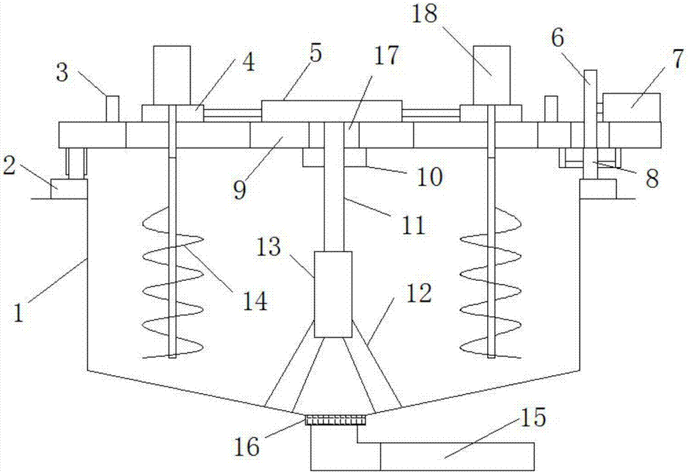
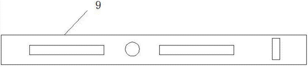
[0016] refer to Figure 1-2 , the invention discloses a sludge mixing tank, comprising a beam 9, a sludge tank 1 is arranged below the beam 9, two agitators 14 are symmetrically arranged at the lower end of the beam 9, and are used for stirring sludge, and the upper end of the beam 9 The slide block 4 corresponding to the two agitators 14 is slidably provided to support the movement of the second motor 18, and the side of the two slide blocks 4 away from the agitator 14 is fixedly connected with the second motor 18, as the agitator 14. Power input, the output shafts of the two second motors 18 are fixedly connected to the upper ends of the two agitators 14, and a dou...


PUM


Abstract

The invention discloses a sludge stirring tank. The sludge stirring tank comprises a cross beam, wherein a sludge tank is arranged below the cross beam; two stirring devices are symmetrically arrangedat the lower end of the cross beam; sliding blocks corresponding to the two stirring devices are arranged at the upper end of the cross beam in a sliding manner; a second motor is fixedly connected to one side, far away from each stirring device, of each of the two sliding blocks; output shafts of the two second motors are fixedly connected to the upper ends of the two stirring devices; a double-head hydraulic cylinder is arranged between the two sliding blocks and is fixedly connected to the upper end of the cross beam; a telescoping rod of the double-head hydraulic cylinder is fixedly connected to the two sliding blocks; and a limiting block which is fixed to the upper end of the cross beam is arranged at one side, far away from the double-head hydraulic cylinder, of each of the two sliding blocks. The sludge stirring tank is novel in structure; the two stirring devices can revolute in the sludge tank while rotating, and the stirring radius can be adjusted, so that the stirring canbe completely performed; and the sludge stirring tank is easy to popularize.

Description

technical field [0001] The invention relates to the field of sewage treatment, in particular to a sludge stirring tank. Background technique [0002] With the development of society, sewage treatment is an important part of environmental protection. Most of the current sewage treatment manufacturers use automated equipment for daily production operations, which greatly improves work efficiency. However, for the sludge in the current sewage treatment Most of the mixing work is done by manpower, so in the actual operation process, the labor consumption is large, and the working environment smells bad. At the same time, the manual mixing effect is poor, and it cannot meet the requirements of the sludge concentration and dehydration operation in the next step. Contents of the invention [0003] The purpose of the present invention is to solve the shortcomings in the prior art, and propose a sludge mixing tank. [0004] In order to achieve the above object, the present inventi...

Claims


Application Information

Patent Timeline
IPC IPC(8): B01F7/16B01F7/30B01F3/22B01F15/00C02F11/00B01F23/80
CPCC02F11/00B01F23/808B01F27/114B01F27/2322B01F27/805B01F27/85B01F27/953B01F27/951B01F35/187
Inventor 吴小飞
Owner 合肥挺泰环保科技有限公司
Why Eureka
Try Eureka