Pipe fitting inner wall machining device

A processing device and a technology for pipe fittings, applied in the field of pipe fitting processing, can solve the problems of high use cost, complicated operation, affecting the powder coating effect, etc., and achieve the effect of reducing input cost, improving processing efficiency, and realizing automatic conversion.

Inactive Publication Date: 2018-05-04
陈军
View PDF8 Cites 12 Cited by
  • Summary
  • Abstract
  • Description
  • Claims
  • Application Information

AI Technical Summary

Problems solved by technology

The inner wall of the pipe fitting needs to be polished before powder coating to remove acne. However, the structure of the existing grinding device is relatively simple, and it is difficult to achieve an ideal polishing effect. In order to improve the coating effect, there are

Method used


Image

  • Pipe fitting inner wall machining device
  • Pipe fitting inner wall machining device

Examples


Embodiment Construction

[0019] All features disclosed in this specification, or steps in all methods or processes disclosed, may be combined in any manner, except for mutually exclusive features and / or steps.

[0020] Any feature disclosed in this specification (including any appended claims, abstract and drawings), unless expressly stated otherwise, may be replaced by alternative features which are equivalent or serve a similar purpose. That is, unless expressly stated otherwise, each feature is one example only of a series of equivalent or similar features.

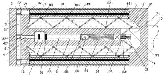
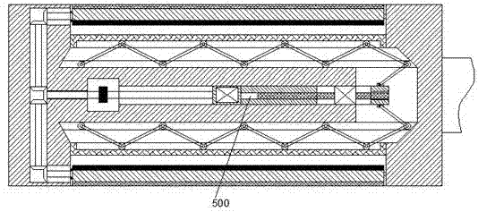
[0021] Such as Figure 1-2 As shown, a pipe fitting inner wall processing device of the device of the present invention includes a rotating cylinder 7 connected to a driving device through a rotating arm 10, and the rotating cylinder 7 is symmetrically provided with mounting grooves 8 opening outward, and the mounting grooves 8 is provided with a conversion structure, and the movable groove 9 connected to the installation groove 8 is arranged...


PUM


Abstract

The invention discloses a pipe fitting inner wall machining device. The pipe fitting inner wall machining device comprises a rotation barrel connected with a drive device through a rotation arm. Installing grooves with outward openings are formed in the rotation barrel in an up-down symmetry manner. A transformation structure is arranged in each installing groove. Movable grooves communicating with the installing grooves are formed in the rotation barrel in an up-down symmetry manner. Each movable groove is provided with a jacking structure. The part, located between the upper movable groove and the lower movable groove, in the rotation barrel is provided with a sliding groove. The sliding groove is internally provided with a drive structure. The part, on the right side of the sliding groove, in the rotation barrel is internally provided with a cavity communicating with the movable grooves. The right side end of the sliding groove extends into the cavity. The drive structure comprisesa first motor fixedly arranged in the sliding groove, a sliding sleeve and a sliding block, wherein the sliding sleeve and the sliding block are arranged in the sliding groove in a sliding manner andlocated on the left side and the right side of the first motor. Threaded holes are formed in the sliding sleeve and the sliding block, and threaded rods are arranged in the threaded holes in a threaded fit manner.

Description

technical field [0001] The invention relates to the field of pipe fitting processing, in particular to a pipe fitting inner wall processing device. Background technique [0002] During the processing of pipe fittings, it is often necessary to carry out anti-corrosion operations on its inner wall. Traditionally, anti-corrosion and anti-oxidation purposes are generally achieved by powder-coating anti-corrosion paint on the inner wall of pipe fittings. The inner wall of the pipe fitting needs to be polished before powder coating to remove acne. However, the structure of the existing grinding device is relatively simple, and it is difficult to achieve an ideal polishing effect. In order to improve the coating effect, there are many cleaning devices used to clean the inner wall of the polished pipe fittings, but the operation is extremely complicated and the cost of use is high. Therefore, the traditional processing device for the inner wall of pipe fittings has major defects and...

Claims


Application Information

Patent Timeline
IPC IPC(8): B08B9/043B24B5/40
CPCB08B9/0436B24B5/40
Inventor 陈军朱晓凤
Owner 陈军
Why Eureka
Try Eureka