Double-end copper wire large drawing mill

A large drawing machine and copper wire technology, applied in wire drawing dies, metal wire drawing, manufacturing tools, etc., can solve the problems of inconvenient drawing, stuck, large investment, etc., and achieve good stability, balanced force, and small friction Effect

Inactive Publication Date: 2018-05-04
江映月
View PDF0 Cites 0 Cited by
  • Summary
  • Abstract
  • Description
  • Claims
  • Application Information

AI Technical Summary

Problems solved by technology

This kind of large drawing machine has the following problems: Since the incoming wire guide wheel, wire drawing wheel, wire drawing die base, outgoing wire sizing die and fixed speed wheel all adopt a single-head structure, only one can be drawn at a time, and the production efficiency is low.
And it covers a large area and invests a lot
Due to the stability of production, the mechanical and electrical properties of the finished wire are difficult to be uniform, which in turn affects the production quality of the subsequent process, such as broken wires and other problems, and the final electrical properties of the cable
In order to improve the efficiency of copper wire drawing, a large double-head drawing machine has appeared on the market, which can draw two copper wires at the same time. The drawing wheel still adopts the traditional unilateral fixing method, which has poor stability, and causes differences in the force of the two copper wires drawn, and there are also subtle differences between the two copper wires, which will cause inconvenience to the subsequent fine drawing. It affects the quality stability of copper wire products, and the existing double-headed drawing machine uses three guide wheels to enter the wire. The advantage of the guide wheel entering the wire is that it is easy to install the first wiring. The wheel is easily damaged due to high force, and the copper material is not straightened. When the copper material is bent, it is easy to jump wires, or it is squeezed and stuck at the edge of the two guide wheels.

Method used


Image

  • Double-end copper wire large drawing mill
  • Double-end copper wire large drawing mill
  • Double-end copper wire large drawing mill

Examples


Embodiment Construction

[0019] For ease of understanding, the present invention will be further explained in detail below in conjunction with the accompanying drawings.

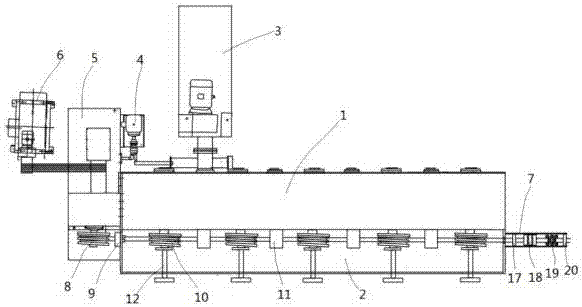
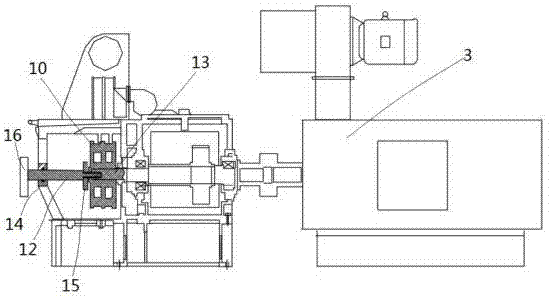
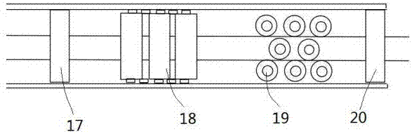
[0020] A double-ended copper wire drawing machine, such as figure 1 , 2 As shown in .3, it includes a large drawing machine body 1, the large drawing machine body 1 is provided with a drawing box 2, and a plurality of drawing wheels 10 are arranged in the drawing box 2, and the drawing wheels 10 are provided with two drawing grooves, adjacent to the drawing box A wire drawing die 11 is arranged between the wheels 10, the wire drawing die 11 is provided with two wire drawing holes, the left end of the drawing box 2 is provided with an outlet die 9, and the right end of the drawing box 2 is equipped with a wire inlet device 7, which includes The first wire entry die 20, the vertical straightening roller system 19, the horizontal straightening roller system 18, and the second wire entry die 17 are arranged in sequence in the moving di...


PUM


Abstract

The invention belongs to the technical field of copper processing and relates to a double-end copper wire large drawing mill. The double-end copper wire large drawing mill comprises a large drawing mill body. The large drawing mill body is provided with a drawing box. Multiple wire drawing wheels are arranged in the drawing box. Each wire drawing wheel is provided with two wire drawing grooves. Awire drawing mold is arranged between every two adjacent wire drawing wheels. Each wire drawing mold is provided with two wire drawing holes. A wire outlet mold is arranged at the left end of the drawing box, and a wire inlet device is mounted at the right end of the drawing box. The wire inlet device comprises a first wire inlet mold, a vertical straightening roller system, a horizontal straightening roller system and a second wire inlet mold, wherein the first wire inlet mold, the vertical straightening roller system, the horizontal straightening roller system and the second wire inlet moldare sequentially arranged in the movement direction of copper wires. Multiple auxiliary fixing bearings are mounted on the outer wall of the drawing box. A wire drawing wheel auxiliary fixing shaft ismounted in each auxiliary fixing bearing. The front end of each wire drawing wheel auxiliary fixing shaft is matched with a connection inner hole in the front end of wire drawing wheel rotating shaft. The double-end copper wire large drawing mill is good in wire inlet stability; the phenomenon that the double-end copper wire large drawing mill gets stuck is avoided; in addition, the wire drawingmolds and the wire drawing wheels are mounted stably; and the two drawn copper wires are good in synchronism and stable in quality.

Description

technical field [0001] The invention belongs to the technical field of copper processing, and relates to a large double-head copper wire drawing machine. Background technique [0002] Copper Traditional copper wire processing equipment, the large drawing machine is a single-head large drawing machine, which consists of a wire guide wheel, a main motor, a segmented splicing gear box, a wire drawing die base, a wire drawing wheel, a segmented water tank, and a constant speed part and fixed speed motor. After the main motor changes speed through the gear box, it drives the wire drawing wheels at different levels respectively. Through the wire drawing wheel and the wire drawing die inside the wire drawing die base, the 8 mm rod is drawn step by step into a wire within the range of 1.2 to 3.5 mm, or directly used as a finished product. , or through a medium drawing machine or a small drawing machine to make thinner copper wires. This large drawing machine has the following prob...

Claims


Application Information

Patent Timeline
Patent Type & Authority Applications(China)
IPC IPC(8): B21C1/04B21C19/00B21C3/02B21C9/00
CPCB21C1/04B21C3/02B21C9/00B21C19/00
Inventor 江映月
Owner 江映月
Why Eureka
Try Eureka