Improved slitting device

A technology for guide rails and workbenches, which is applied to work accessories, manufacturing tools, stone processing equipment, etc., can solve the problems of low work efficiency and high labor intensity of workers, and achieve the effect of simple structure, reduced labor efficiency, and reduced labor intensity.

Inactive Publication Date: 2018-05-04
宁波泰芸电气有限公司
View PDF0 Cites 3 Cited by
  • Summary
  • Abstract
  • Description
  • Claims
  • Application Information

AI Technical Summary

Problems solved by technology

[0003] The invention provides an improved cutting device, which solves the technical problems of high labor intensity and low work efficiency in the prior art

Method used


Image

  • Improved slitting device

Examples


Embodiment Construction

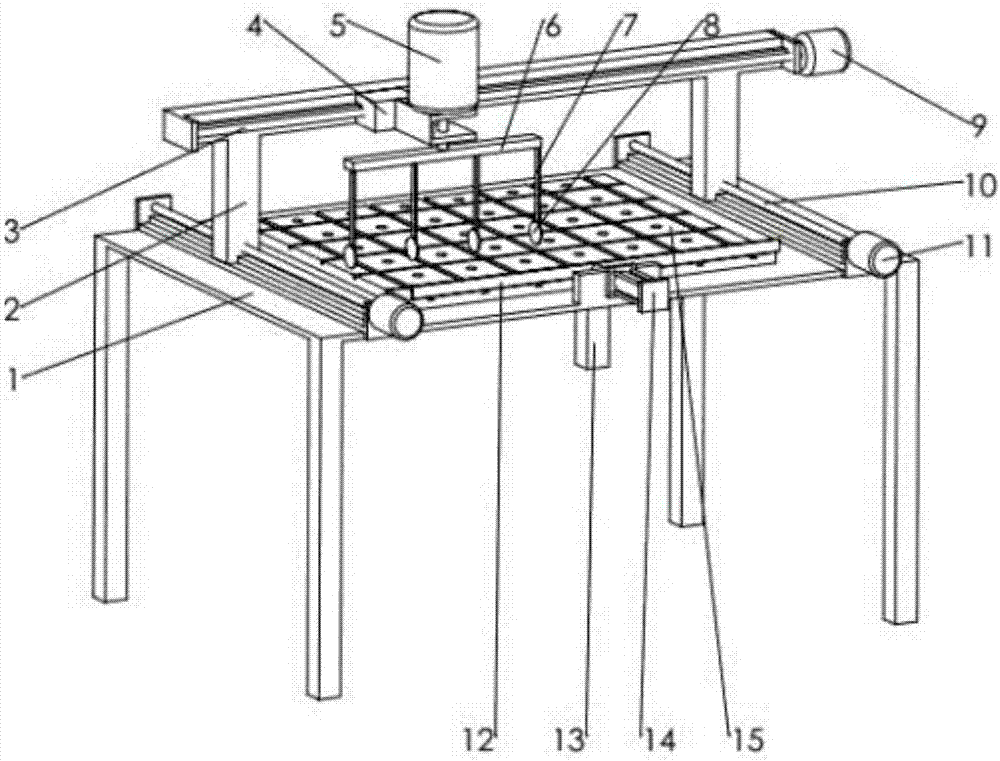
[0012] combined with figure 1 An improved cutting device of the present invention will be further described.

[0013] An improved slitting device, including a workbench 1, two mutual first guide rails are installed on the workbench 1, a vacuum suction cup 15 is installed between the two first guide rails, and a vacuum generator is also installed on the workbench 1 13. The vacuum generator 13 communicates with the vacuum suction cup 15. A support 2 is also installed on the first guide rail. The support 2 is also provided with a support drive mechanism. The support 2 is also provided with a second guide rail that is horizontally arranged and perpendicular to the first guide rail. , a slider 4 is installed on the second guide rail, a slider drive mechanism is provided on the slider 4, a support rod 6 is also horizontally and rotatably installed on the slider 4, and a plurality of vertically arranged The connecting rod 7 is equipped with a cutting wheel 8 at the lower end of each...


PUM


Abstract

The invention discloses an improved slitting device which comprises a working table. The working table is provided with two first guide rails, a vacuum chuck is installed between the two first guide rails, the working table is further provided with a vacuum generator, the vacuum generator is communicated with the vacuum chuck, a support is further installed on the first guide rails, a support driving mechanism is arranged on the support, the support is provided with a second guide rail which is horizontally arranged and is vertical to the first guide rail, a sliding block is installed on the second guide rail and is provided with a sliding block driving mechanism, the sliding block is horizontally and rotationally provided with a supporting rod, the supporting rod is sequentially and evenly provided with a plurality of vertically arranged connecting rods, and the lower end of each connecting rod is provided with a cutting wheel; and a first motor is further included, the supporting rodis driven by the first motor, and the working table is further provided with a pushing mechanism. The improved slitting device is simple in structure and very practical.

Description

technical field [0001] The invention relates to the technical field of wall brick manufacturing equipment, in particular to an improved cutting device. Background technique [0002] One of the wall tiles is the mosaic wall tile, which divides the glass into multiple small pieces, and then arranges them for bonding and drying. The existing equipment is manually cut when cutting. Slitting in both horizontal and vertical directions, such a slitting method not only has high work intensity, but also has low work efficiency, which is not suitable for mass production. Contents of the invention [0003] The invention provides an improved cutting device, which solves the technical problems of high labor intensity and low work efficiency in the prior art. [0004] The technical solutions of the present invention are as follows: an improved slitting device includes a workbench, two mutual first guide rails are installed on the workbench, a vacuum suction cup is installed between the...

Claims


Application Information

Patent Timeline
Patent Type & Authority Applications(China)
IPC IPC(8): B28D1/24B28D7/04B28D7/00
CPCB28D1/24B28D7/00B28D7/04B28D7/046
Inventor 陈杰
Owner 宁波泰芸电气有限公司
Why Eureka
Try Eureka