
Multi-spray-head pressing type 3D printer and printing method

A 3D printer, compact technology, applied in the direction of 3D object support structures, manufacturing tools, coating devices, etc., can solve the problem of items that are not suitable for printing powdery raw materials, not suitable for printing metal molds, and can not solve the problem of layer and layer. Combining problems and other problems to achieve the effect of improving printing efficiency, combining tightness and preventing environmental pollution

Pending Publication Date: 2018-05-04
KEDA INDUSTRIAL GROUP CO LTD
View PDF7 Cites 8 Cited by
  • Summary
  • Abstract
  • Description
  • Claims
  • Application Information

AI Technical Summary

Problems solved by technology

However, the above-mentioned technical solutions are not suitable for printing powdery raw materials, and cannot solve the problem of bonding between layers. The above-mentioned technical solutions are not suitable for printing metal molds, ceramic products, knives, kitchen utensils and other products that use powder materials as original materials.

Method used


Image

  • Multi-spray-head pressing type 3D printer and printing method
  • Multi-spray-head pressing type 3D printer and printing method
  • Multi-spray-head pressing type 3D printer and printing method

Examples


Embodiment 1

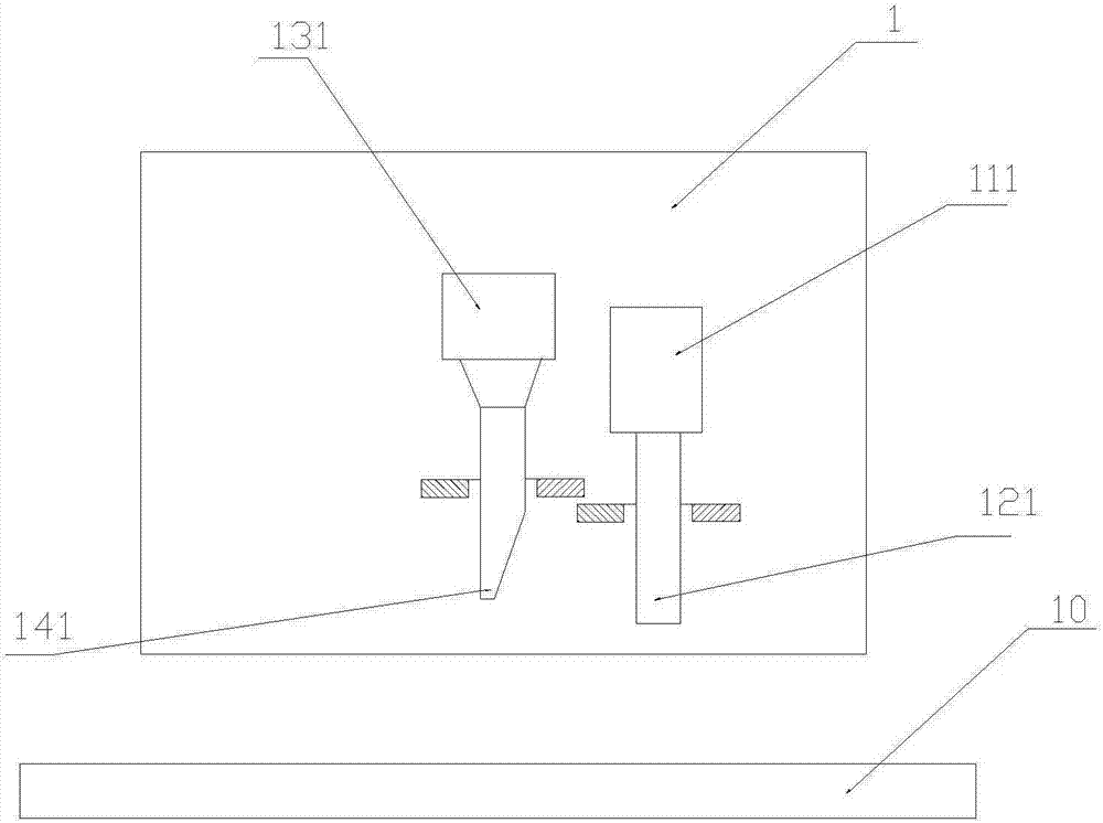
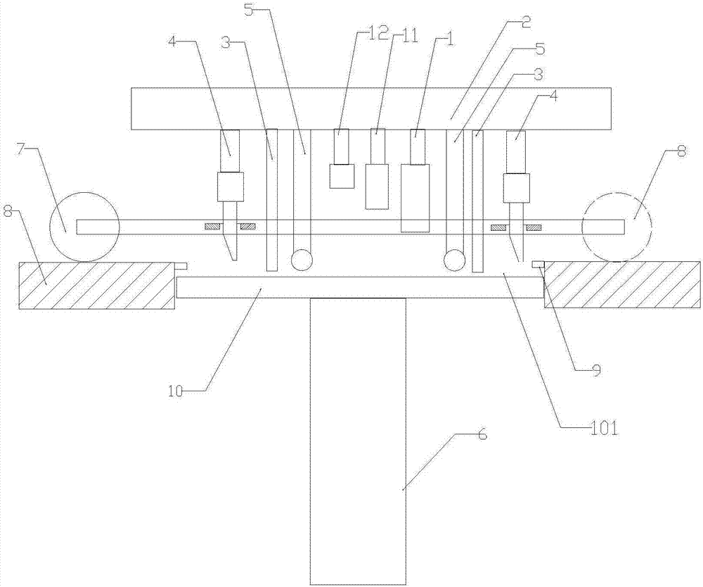
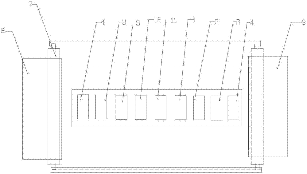
[0042] see Figure 1-3 , this embodiment discloses a multi-nozzle compact 3D printer, which includes a mobile platform 10, a vacuum chamber, and a plurality of printing modules 1, 11, 12, . . . , N. The plurality of printing modules are all arranged in a vacuum chamber, and are arranged sequentially above the mobile platform 10, the printing module 1 with the smallest distance from the moving platform 10 is the first printing module, and the printing module 1 next to the first printing module 1 The printing module is the second printing module 11, and so on, and the printing module with the largest distance from the mobile platform 10 is the Nth printing module. The above-mentioned mobile platform 10 is a horizontally arranged platform that can be raised and lowered. A plurality of the printing modules are sequentially arranged in a straight line above the mobile platform 10, and from the first printing module 1 to the Nth printing module, the distance between the moving The ...

Embodiment 2

[0051] Such as Figure 4As shown, the difference from Embodiment 1 is that a polygonal through hole is set in the middle of the fixed platform 8 of this embodiment, preferably a rectangular through hole, and the shape of the mobile platform 10 is the same as that of the through hole. 10 is placed in the through hole and clings to the inner wall of the through hole. A printing cavity 101 is formed between the moving platform 10 and the inner wall of the through hole, and the printing module realizes reciprocating layer-by-layer printing in the printing cavity 101 .

Embodiment 3

[0053] see Figure 5 and 6 , this embodiment discloses a multi-nozzle compact 3D printer, which includes a mobile platform 10, a vacuum chamber, and multiple printing modules 1, 11, 12...,N. The plurality of printing modules are all arranged in a vacuum chamber, and are arranged sequentially above the mobile platform 10, the printing module 1 with the smallest distance from the mobile platform 10 is the first printing module, and the distance between the mobile platform 10 and the printing module 1 is the first printing module. The printing module 11 with the next smallest distance is the second printing module, and so on, the printing module with the largest distance from the mobile platform 10 is the Nth printing module.

[0054] The difference from Embodiment 1 is that the mobile platform 10 of this embodiment is circular, and the fixed platform 8 is provided with a circular through hole, and the mobile platform 10 moves up and down in the circular through hole, and is in ...


PUM


Abstract

The invention discloses a multi-spray-head pressing type 3D printer which comprises a printing machine frame arranged in a vacuum chamber. A printing module set is arranged above the printing machineframe and comprises multiple printing modules arranged on a printing platform used for bearing printed products, the distance between the printing modules and the printing platform is sequentially increased, and the printing modules and the printing platform can move relatively. The printing platform comprises a fixed platform and a movable platform. A printing cavity is formed between the fixed platform and the movable platform which moves up and down. A printing spray head carried out printing in the printing cavity. The printer is further provided with a scraper blade device, a pressing roller and a laser device, a single printing layer is scraped and pressed, the distance between material layers of printed materials and the gap between powder granules can be compressed, powder granulescan be more compactly combined, and the printing efficiency is greatly improved since the multiple printing modules are adopted for printing simultaneously.

Description

technical field [0001] The invention relates to the field of 3D printers, in particular to a multi-nozzle compact 3D printer and a printing method thereof. Background technique [0002] In the prior art, metal moulds, ceramic supplies, knives, kitchen utensils and other articles are produced by means of traditional sand molding methods, which are very low in efficiency and high in cost. [0003] 3D printing is a kind of rapid prototyping technology. It is a technology based on digital model files and using bondable materials such as powdered metal or plastic to construct objects by layer-by-layer printing. [0004] The 3D printer reads the cross-sectional information in the file, prints these cross-sections layer by layer with liquid, powdery or sheet materials, and then glues the cross-sections of each layer in various ways to create an entity. The peculiarity of this technique is that it can create objects of almost any shape. 3D printing is often used to manufacture mod...

Claims


Application Information

Patent Timeline
Patent Type & Authority Applications(China)
IPC IPC(8): B29C64/135B29C64/20B29C64/209B29C64/35B33Y30/00B33Y40/00B33Y10/00
CPCB33Y10/00B33Y30/00
Inventor 武桢
Owner KEDA INDUSTRIAL GROUP CO LTD
Learn More