
Cloth boiling and dyeing device

A dyeing device and a technology for cooking cloth, applied in the field of cloth processing, can solve the problems of uneven dyeing of cloth, low degree of dyeing, increase of cloth processing procedures and processing costs, etc., and achieve the effect of facilitating dyeing and reducing processing procedures.

Active Publication Date: 2018-05-04
NINGBO HIGH TECH ZONE SHENGWENTU TEXTILE CO LTD
View PDF6 Cites 3 Cited by
  • Summary
  • Abstract
  • Description
  • Claims
  • Application Information

AI Technical Summary

Problems solved by technology

Because there are a lot of fabrics to be dyed, a large number of fabrics are easy to be stacked together during the dyeing process, which will easily lead to a low degree of dyeing in the piled parts of the fabrics. The fabrics on the surface can fully contact with the dyes, which can achieve better exhaust dyeing. When the fabric is observed as a whole, it will be found that the dyeing of the fabric is uneven; at the same time, due to the phenomenon of stacking of the fabric during the dyeing process, many wrinkles can be found on the fabric after taking out the fabric after dipping
[0003] When the dyeing of the fabric is uneven, it is necessary to continuously turn the fabric over to make the fabric evenly contact with the dye. During this process, the fabric will still be wrinkled. After finishing the dyeing process of the fabric, the fabric needs to be ironed. Greatly increase the processing procedure and processing cost of the fabric

Method used


Image

  • Cloth boiling and dyeing device
  • Cloth boiling and dyeing device

Examples


Embodiment Construction

[0017] Further detailed explanation through specific implementation mode below:

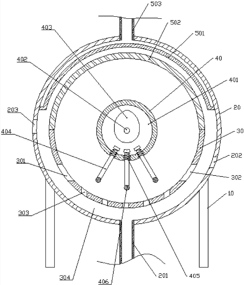
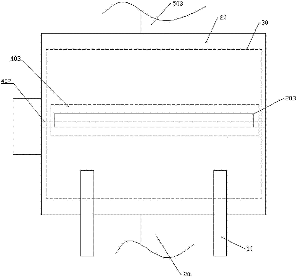
[0018] The reference signs in the drawings of the description include: frame 10, outer cylinder 20, water inlet pipe 201, second inlet 202, second outlet 203, inner cylinder 30, first inlet 301, first outlet 302, through hole 303, Dye chamber 304, fixed shaft 40, accommodating chamber 401, rotating shaft 402, cam 403, slide bar 404, spring 405, kneading ball 406, first heating wire 501, second heating wire 502, air outlet pipe 503.

[0019] The embodiment is basically as attached figure 1 And attached figure 2 Shown: boiled cloth dyeing device, including frame 10, including dyeing mechanism, extruding mechanism and drying mechanism.

[0020] The dyeing mechanism includes an outer cylinder 20, a water inlet pipe 201, an inner cylinder 30 and a fixed shaft 40. The fixed shaft 40 is arranged horizontally. Between, and form dye chamber 304 between outer cylinder 20 and inner cylinder 30, the oute...


PUM


Abstract

The invention relates to the field of cloth processing, in particular to a cloth boiling and dyeing device. The device includes an outer cylinder, a water inlet pipe, an inner cylinder, a fixing shaft, a first electric heat wire and an air outlet pipe; the outer cylinder and the inner cylinder are sequentially, coaxially and fixedly installed on the fixing shaft from outside to inside, and the outer cylinder and the inner cylinder form a dye cavity; the outer wall of the outer cylinder is fixedly connected with a machine frame, the upper end of the water inlet pipe is communicated with the lower side of the outer cylinder, the side face of the inner cylinder is provided with a first inlet and a first outlet which are communicated with the inner cylinder, and the first inlet and the first outlet are formed in the two sides of the vertical diameter of the cross section of the inner cylinder; the outer cylinder is provided with a second outlet near the first outlet, the outer cylinder isprovided with the second outlet near the first inlet, the first electric heat wire is fixedly installed on the inner wall of the upper side of the outer cylinder, the air outlet pipe is communicated with the upper side of the outer cylinder, and the air outlet pipe is communicated with the air inlet pipe. According to the scheme, the situation that cloth generates wrinkles in the dyeing process can be avoided.

Description

technical field [0001] The invention belongs to the field of cloth processing, and in particular relates to a cloth cooking and dyeing device. Background technique [0002] When dyeing cloth, generally dye and water are mixed, then the mixed dye is put into the dyeing tank, a large amount of cloth to be dyed is placed in the dyeing tank, a large amount of dyes to be dyed in the dyeing tank The fabric is dip-dyed. Because there are a lot of fabrics to be dyed, a large number of fabrics are easy to be stacked together during the dyeing process, which will easily lead to a low degree of dyeing in the piled parts of the fabrics. The fabrics on the surface can fully contact with the dyes, which can achieve better exhaust dyeing. When the fabric is observed as a whole, it will be found that the dyeing of the fabric is uneven; at the same time, due to the phenomenon of stacking of the fabric during the dyeing process, many wrinkles can be found on the fabric after taking out the f...

Claims


Application Information

Patent Timeline
IPC IPC(8): D06B23/18D06B21/00D06B5/08D06B23/04D06B19/00D06B15/00D06B23/20
CPCD06B5/08D06B15/00D06B19/0029D06B21/00D06B23/04D06B23/18D06B23/20D06B2700/36
Inventor 孙文清
Owner NINGBO HIGH TECH ZONE SHENGWENTU TEXTILE CO LTD
Learn More