Novel high-speed rail subgrade pipe-roof-type chemical grouting system
A technology for high-speed railway foundation and grouting system, which is applied in the direction of roads, infrastructure engineering, soil protection, etc., can solve problems such as insufficient material flow, inability to ensure smooth grouting work, and inability to control grouting pressure. The effect of stable material flow
- Summary
- Abstract
- Description
- Claims
- Application Information
AI Technical Summary
Problems solved by technology
Method used
Image

Examples
Embodiment 1
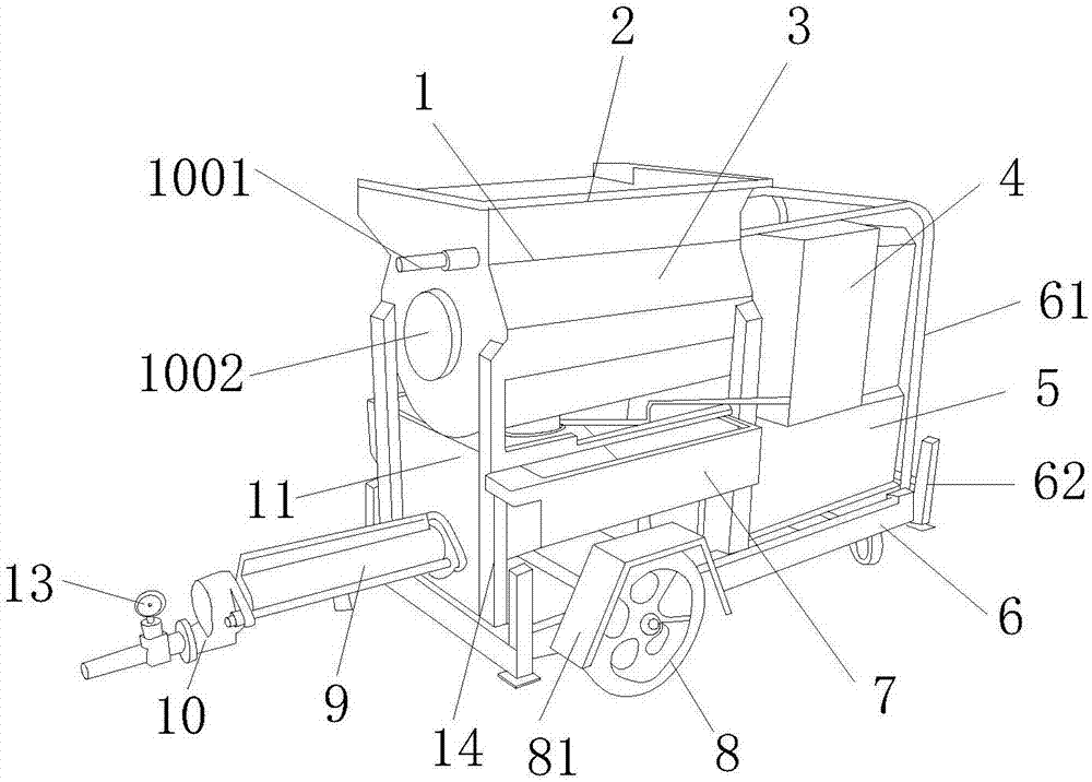
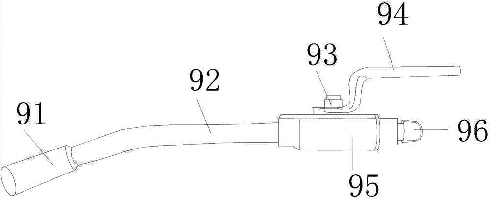
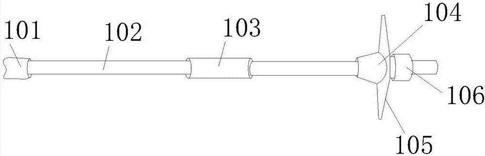
[0036] see Figure 1 to Figure 8 , the present invention provides a new high-speed railway base pipe shed type chemical grouting system technical solution: its structure includes a grouting machine body 1, a grouting feeding tank 2, a screw type grouting booster device 3, a controller 4, and an electric control box 5. Fixed base 6, lower hopper 7, casters 8, grouting high-pressure valve stem 9, self-advancing grouting gun head 10, mixing tank 11, quantitative grouting bucket 12, high pressure gauge 13, frame 14, the The grouting feeding tank 2 is arranged on the top of the grouting machine body 1, the grouting machine body 1 and the grouting feeding tank 2 are parallel to each other, the side end of the grouting machine body 1 is provided with a quantitative grouting barrel 12, and the screw Type grouting booster device 3 is installed inside the grouting machine body 1, the four corners of the grouting machine body 1 are welded to the frame 14, and the grouting machine body 1 ...
Embodiment 2
[0042] see Figure 9 , in order to make the grouting process of the railway base pipe shed more convenient, the grouting is provided by the quantitative grouting bucket 12 for grouting, and the quantitative delivery is carried out, and the control chip of the quantitative controller 127 sends a signal instruction to control the rotation of the vibrator 1002 Perform vibration grouting.
[0043] Such as Figure 9 As shown: the quantitative grouting tank 12 is composed of a first slurry delivery pipe 121, a second slurry delivery tube 122, a slurry storage tank 123, a slurry guide frame 124, a motor 125, a display screen 126, a quantitative controller 127, and a bracket 128 , the quantitative controller 127 is fixedly installed on the outer layer of the slurry storage tank 123, the top of the slurry storage tank 123 is provided with a motor 125, the bottom of the slurry storage tank 123 is welded to the bracket 128, and the side end of the slurry storage tank 123 Welded with th...
PUM
 Abstract
Description
Claims
Application Information
 - R&D Engineer
- R&D Manager
- IP Professional
- Industry Leading Data Capabilities
- Powerful AI technology
- Patent DNA Extraction
Browse by: Latest US Patents, China's latest patents, Technical Efficacy Thesaurus, Application Domain, Technology Topic.
© 2024 PatSnap. All rights reserved.Legal|Privacy policy|Modern Slavery Act Transparency Statement|Sitemap