Enclasping type anti-loosening bolt pair
A technology for preventing loosening of bolts and bolts, applied in the direction of bolts, screws, nuts, etc., can solve the problem of no structural improvement.
- Summary
- Abstract
- Description
- Claims
- Application Information
AI Technical Summary
Problems solved by technology
Method used
Image
Examples
Embodiment 1
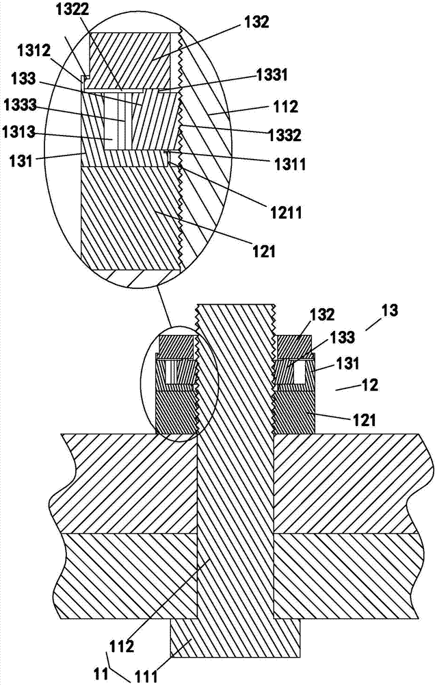
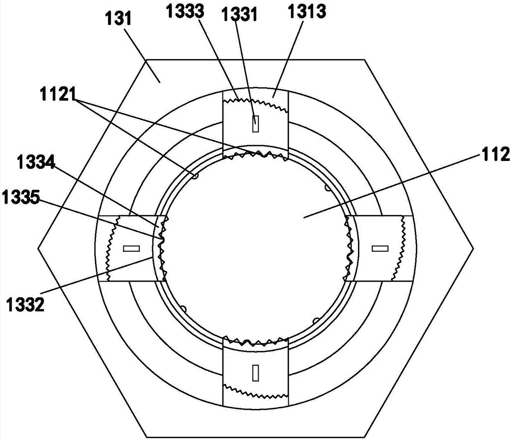
[0046] A kind of clamping anti-loosening bolt pair, such as figure 1 and figure 2 As shown, it includes a bolt 11 and a nut 12. The bolt 11 includes a bolt head 111 of an integral structure and a bolt shank 112 provided with an external thread extending to the end. The nut 12 is screwed on the bolt shank 112, and the nut 12 It includes a nut body 121 and a gripping mechanism 13 arranged on one end surface of the nut body 121 that can be adjusted to grip the bolt rod 112 .
[0047] In this embodiment, the clasping mechanism 13, such as figure 1 and figure 2As shown, it includes a first adjustment ring 131, a second adjustment ring 132 and a clamping block 133, the first adjustment ring 131 is arranged between the second adjustment ring 132 and the nut body 133, the first adjustment ring 131 and the nut body 133 The nut bodies 131 are connected in a relatively rotatable manner, and the first adjustment ring 131 and the second adjustment ring 132 are connected in a relativel...
Embodiment 2
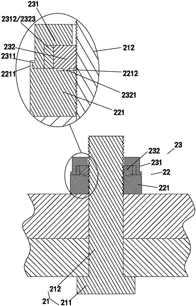
[0053] A kind of clamping anti-loosening bolt pair, such as image 3 and Figure 4 As shown, it includes a bolt 21 and a nut 22. The bolt 21 includes a bolt head 211 of an integral structure and a bolt shaft 212 provided with an external thread extending to the end. The nut 22 is screwed on the bolt shaft 212, and the nut 22 It includes a nut body 221 and a gripping mechanism 23 arranged on one end surface of the nut body 221 that can be adjusted to grip the bolt rod 212 .
[0054] In this embodiment, the gripping structure 23, such as image 3 and Figure 4 As shown, it includes an adjustment ring 231 and a tight block 232. The adjustment ring 231 is connected to the nut body 221 in a relatively rotatable manner. As shown in the figure, it is specifically the outer surface of the lower end of the adjustment ring 231. A step ring 2311 is protruded upward, and a riveting edge 2211 for riveting and hooking on the step ring 2311 is protruded on the nut body 221; the clamping b...
PUM
 Abstract
Description
Claims
Application Information
 - R&D
- Intellectual Property
- Life Sciences
- Materials
- Tech Scout
- Unparalleled Data Quality
- Higher Quality Content
- 60% Fewer Hallucinations
Browse by: Latest US Patents, China's latest patents, Technical Efficacy Thesaurus, Application Domain, Technology Topic, Popular Technical Reports.
© 2025 PatSnap. All rights reserved.Legal|Privacy policy|Modern Slavery Act Transparency Statement|Sitemap|About US| Contact US: help@patsnap.com


