
Air conditioner frame fixing device

A technology for fixing devices and air-conditioning racks, which can be used in space heating and ventilation details, household heating, lighting and heating equipment, etc., and can solve problems such as heat generation, damage to air-conditioning components, and reduced service life of air-conditioners

Inactive Publication Date: 2018-05-04
重庆晓微城企业孵化器有限公司
View PDF11 Cites 0 Cited by
  • Summary
  • Abstract
  • Description
  • Claims
  • Application Information

AI Technical Summary

Problems solved by technology

[0004] The above-mentioned patent document avoids the stagnation of water through the oblique water guide surface of the right-angled trapezoidal support frame, and the use of the hollow right-angled trapezoidal body can ensure that the support frame bears force while reducing the self-weight of the support frame and reducing materials. However, the right-angled trapezoidal The support frame is made of steel structure. When the water continues to flow along the oblique guide of the support frame, the water will have contact with the oblique guide of the support frame, and a small amount of water will stay in the oblique guide of the support frame, eventually causing the support frame to On the other hand, when the air conditioner is turned on, it will produce a lot of noise, and the sound waves generated by the noise will drive the air conditioner to vibrate. Generate friction, and then generate heat, damage the air conditioner components, and reduce the service life of the air conditioner

Method used


Image

  • Air conditioner frame fixing device
  • Air conditioner frame fixing device

Examples


Embodiment Construction

[0023] Further detailed explanation through specific implementation mode below:

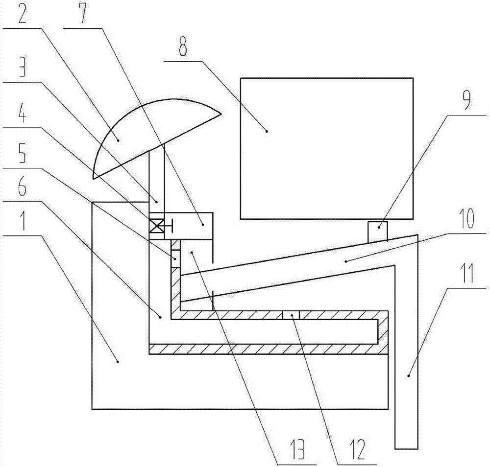
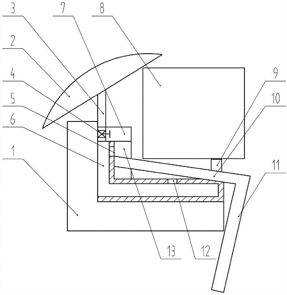
[0024] The reference signs in the drawings of the description include: air conditioner frame 1, water bag 2, water delivery pipe 3, pressure valve 4, water inlet hole 5, water storage cavity 6, box body 7, air conditioner 8, top block 9, pressure plate 10, Limiting plate 11, water outlet hole 12, chute 13.

[0025] Note: The up, down, left, and right in this embodiment are subject to the up, down, left, and right in the drawings.

[0026] The embodiment is basically as attached figure 1 As shown: the fixing device of the air-conditioning rack, including the water storage chamber 6 arranged on the air-conditioning rack 1 and the air conditioner 8 arranged above the water storage chamber 6, the section of the water storage chamber 6 is horizontal L-shaped, and the water storage chamber 6 is made of plastic material It has a certain degree of elasticity. The water storage chamber 6 includes a vert...


PUM


Abstract

The invention discloses an air conditioner frame fixing device. The fixing device comprises a water storage cavity formed in an air conditioner frame, the water storage cavity is made of a soft plastic material, the water storage cavity comprises a transverse part and a vertical part, a sliding groove is formed outside the vertical part, a pressing plate capable of achieving sliding connection along the sliding groove is arranged in the sliding groove, the pressing plate is arranged in an inclination shape, the pressing plate is located above the transverse part, a water inlet hole formed above the pressing plate is formed in the transverse part, a water outlet hole is formed in the vertical part, and faces the pressing plate, a top block is arranged on the pressing plate, the water storage cavity and the top end of the sliding groove are flush, a box body is arranged above the water storage cavity, the box body is of a hollow structure, a water conveying pipe is arranged in the box body, one end of the water conveying pipe is communicated with the water storage cavity, the other end of the water conveying pipe is sleeved with a water bag, the water bag is arranged in an inclination shape, the section of the water bag is in a semi circular shape, one side of the gas arching portion of the water bag is upward, a pressure valve located on the box body is arranged in the water conveying pipe, heat can be absorbed by rainwater in space below the pressing plate, rainwater can vibrate along with vibration, and through the vibration, rainwater can be more easily brought away by heat generated by the air conditioner.

Description

technical field [0001] The invention belongs to the technical field of air-conditioning brackets, in particular to an air-conditioning bracket fixing device. Background technique [0002] Commonly used air conditioner frames are mostly welded angle steel frames. The outdoor unit of the air conditioner is hung outdoors. Affected by rain or the self-drainage of the air conditioner, the air conditioner frame and the connection between the air conditioner and the air conditioner frame are prone to rust, which will cause the air conditioner frame to be damaged. The stress strength of its own structure is reduced and the firmness of the connection between the air conditioner and the air conditioner frame is reduced, so that the accident of the air conditioner falling is prone to occur. [0003] In order to solve the above technical problems, the Chinese patent document (application number is CN201420242253.5) discloses a steel structure air-conditioning frame, which includes a fix...

Claims


Application Information

Patent Timeline
IPC IPC(8): F24F13/32
Inventor 张振军
Owner 重庆晓微城企业孵化器有限公司
Learn More