Method and device for marking contour of excavation roadway based on adjustment of laser light path

A technology of optical path adjustment and laser marking, which is applied in the direction of using optical devices, measuring devices, instruments, etc., can solve the problems of poor recognition effect, poor versatility, and complicated devices, so as to eliminate errors, eliminate marking errors, and solve the problem of numerous devices Effect

Pending Publication Date: 2018-05-04
CHINA UNIV OF MINING & TECH (BEIJING)
View PDF2 Cites 2 Cited by
  • Summary
  • Abstract
  • Description
  • Claims
  • Application Information

AI Technical Summary

Problems solved by technology

[0005] The purpose of the present invention is to overcome the disadvantages of laser multi-point emission, poor recognition effect, complicated devices and poor versatility in the prior art. The present invention provides a method and device for marking the outline of excavation tunnels based on laser optical path adjustment. Laser Marker

Method used


Image

  • Method and device for marking contour of excavation roadway based on adjustment of laser light path
  • Method and device for marking contour of excavation roadway based on adjustment of laser light path
  • Method and device for marking contour of excavation roadway based on adjustment of laser light path

Examples


Embodiment 1

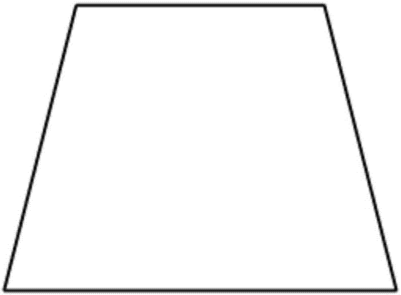
[0048] This embodiment chooses figure 2 The outline of the rectangular excavation roadway is used as the object to be marked. The purpose is to use the laser marking instrument to project a rectangular laser pattern on the head of the roadway to mark the outline of the rectangular excavation roadway.

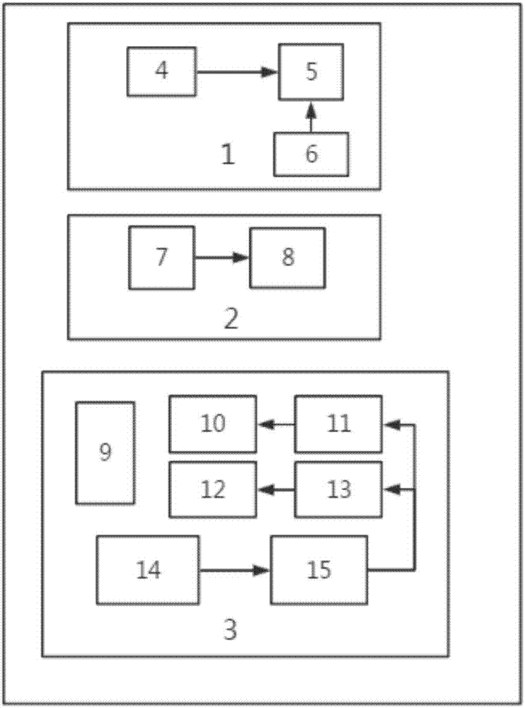
[0049] exist Figure 8 In this embodiment, the working mode in this embodiment is selected as a set of equipment centered projection mode, that is, a set of laser markers is installed at the center position on the top of the roadway, and the grating diffraction optical path adjustment module or the galvanometer in the laser optical path adjustment device is used to scan All optical path adjustment modules can realize the projection of rectangular laser patterns.

[0050] exist Figure 9 Among them, the working mode in this embodiment is selected as two sets of equipment and the projection method is used, that is, two sets of laser marking instruments are used, and the two set...

Embodiment 2

[0055] This embodiment chooses Figure 7 The outline of the excavation roadway with rounded corners is used as the object to be marked. The purpose is to use the laser marking instrument to project a laser pattern in the form of a rounded rectangle on the head of the roadway to mark the outline of the excavated roadway with rounded corners.

[0056] exist Figure 10 In this example, the working mode in this embodiment is selected as two sets of equipment and the projection method is used, that is, two sets of laser marking instruments are used, and the two sets of laser marking instruments are respectively numbered as No. 3 marking instrument and No. 4 marking instrument. The two sets of laser marking instruments The marking instruments are installed on the top of the roadway in a suspended manner, and are respectively located at the left and right top corners of the roadway, respectively projecting the left half and right half of the rounded rectangular pattern, and finally s...


PUM


Abstract

The invention relates to a method and device for marking the contour of an excavation roadway based on adjustment of a laser light path and belongs to the technical field of auxiliary equipment for aheading machine. The device is called a laser marking device, and is essentially a laser light path adjusting device. The device includes a prismatic refractive light path adjusting module, a gratingdiffractive light path adjustment module and a galvanometer scanning light path adjustment module which are totally three function modules. A function of adjusting point laser to a continuous laser line can be achieved, the shortcoming that devices are various and difficult to recognize during multipoint laser transmission is overcome, and roadway contour marking accuracy is improved. The three function modules can be flexibly selected for different shapes of roadway contours, and the device is high in universality. A working mode of simultaneous use of multiple devices is adopted, a laser projection path is optimized, and the working safety is improved. A measurement feedback device in the galvanometer scanning light path adjustment module can be utilized to measure the projection distance and perform feedback to a control device to automatically adjust a projected laser pattern to eliminate errors and solve the real-time follow-up problem in tunneling work.

Description

technical field [0001] The invention belongs to the technical field of roadheader auxiliary equipment, and in particular relates to a method and a device for marking the outline of a roadway. Background technique [0002] At present, due to the large dust and high dust concentration during the roadway excavation, the driver of the roadheader cannot observe the profile of the roadway section, resulting in serious over-excavation and under-excavation. Affected the work efficiency of excavation operation. Therefore, there is an urgent need for a method that can project a laser in the shape of the roadway outline, and provide the roadway outline as a reference for the excavation workers. In actual situations, roadway outline graphics often contain one or more circular arcs, and existing laser projection equipment mostly projects straight-line lasers, such as laser line markers and laser level gauges. For this reason, a roadway excavation based on laser optical path adjustment i...

Claims


Application Information

Patent Timeline
IPC IPC(8): G01B11/25
CPCG01B11/2531
Inventor 郝雪弟张中平李宇航景新平纪伟亮吴淼
Owner CHINA UNIV OF MINING & TECH (BEIJING)
Why Eureka
Try Eureka