hook commutator

A commutator and hook-type technology, which is applied in the direction of current collectors, rotating current collectors, electrical components, etc., can solve problems such as difficult discharge, commutator short circuit, weak hook top strength of welding wire, etc.

Active Publication Date: 2021-09-10
瑞安博宇科技股份有限公司
View PDF5 Cites 0 Cited by
  • Summary
  • Abstract
  • Description
  • Claims
  • Application Information

AI Technical Summary

Problems solved by technology

Since the width of the insulation groove is generally strictly controlled within 0.5mm, and the depth is limited, that is, the space of the insulation groove is narrow and the ventilation conditions are extremely poor, and there are dead corners in the insulation groove, so the carbon powder produced by the carbon brush wear when the motor is working will inevitably be in the air. The accumulation in the insulation groove is not easy to discharge, even if the blowing method is used, the effect is very small; when the toner accumulates in the insulation groove to a certain extent, it is very likely that the short circuit of the commutator will occur
In addition, there is only one welding wire hook on the top of each commutator piece, so that when one commutator piece is spot-welded with two enameled wires, since the two enameled wires need to be arranged up and down, the welding hook is first required. The length must be long enough to cover the two enameled wires. In addition, the connecting semicircle of the upper and lower two enameled wires cannot contact the inner surface of the welding wire hook, so it affects the stability of spot welding and is prone to false welding. In addition, the welding wire After the hook is formed, the hook top of the welding wire hook is an inner and outer arc, and the strength of the hook top of the welding wire hook is weak, so that the force of the welding wire hook will be reversed during the spot welding process, and the enameled wire will be easily compressed. It is damaged, and the inner arc of the hook top is very small, and its arc radius is much smaller than the radius of the enameled wire, so there will be a large gap between the inside of the hook top of the welding wire and the enameled wire, and the two cannot be in good contact. , also prone to virtual soldering phenomenon

Method used


Image

  • hook commutator
  • hook commutator
  • hook commutator

Examples


Embodiment Construction

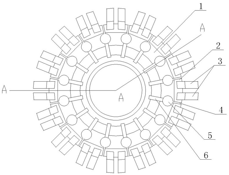
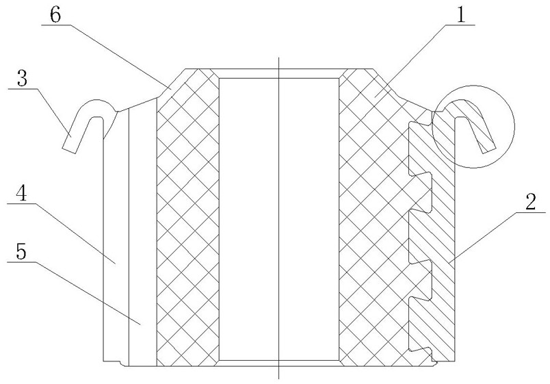
[0014] As shown in the figure, the hook-type commutator of the present invention includes a base body 1 and sixteen commutation segments 2 uniformly arranged on the outer circumference of the base body 1, and insulating grooves 4 are provided between adjacent commutation segments 2 for insulation. , the groove width of the insulating groove 4 is within 0.5 mm, the inner end of the insulating groove 4 is provided with an axial through groove 5, the axial through groove 5 is arranged in the same direction as the insulating groove 4 and penetrates the upper and lower end surfaces of the base body 1, and the upper end surface of the base body 1 The end face has an inclined surface, and a diversion groove 6 is opened on the inclined surface. The upper end of the diversion groove 6 is open, and the lower end of the diversion groove 6 communicates with the axial through groove 5. The axial through groove 5 is designed as a round hole. , the aperture of the axial through groove 5 is no...


PUM


Abstract

The invention discloses a hook-type commutator, which includes a base body and commutation segments uniformly arranged on the outer circumference of the base body, insulating grooves are provided between adjacent commutation segments for insulation, and welding wire hooks are arranged on the top of the commutation segments , characterized in that: the inner side of the insulating groove is provided with an axial through groove, the axial through groove is arranged in the same direction as the insulating groove and runs through the upper and lower end faces of the base body, the upper end face of the base body has a slope, and a guide groove is opened on the slope to guide The upper end of the flow groove is open, and the lower end of the flow guide groove communicates with the axial through groove. The invention can completely solve the problems of carbon deposition and virtual welding in the commutator, thereby eliminating the two most important factors of motor damage, greatly improving and effectively ensuring the service life of the motor, and low production cost.

Description

technical field [0001] The present invention relates to a hook type commutator. Background technique [0002] There are two main factors for the damage of the motor under normal conditions. One is the carbon deposition in the insulation groove of the commutator, which leads to the damage of the motor caused by the short circuit of the commutator; the other is the welding hook of the commutator and the enameled wire of the motor rotor coil. There is a virtual weld between them after spot welding, resulting in motor damage caused by an open circuit. The fundamental reason is that there are certain deficiencies in the structure of the commutator. [0003] The hook-type commutator of the prior art includes a base body and commutator segments uniformly arranged on the outer circumference of the base body, insulation grooves are provided between adjacent commutator segments, and welding wires are provided on the top of the commutator segments hook. Since the width of the insula...

Claims


Application Information

Patent Timeline
Patent Type & Authority Patents(China)
IPC IPC(8): H01R39/04H01R39/32
CPCH01R39/04H01R39/32
Inventor 杨紫妍
Owner 瑞安博宇科技股份有限公司
Why Eureka
Try Eureka