Waste liquid disposal device

A waste liquid treatment and waste liquid technology, applied in the field of waste liquid treatment devices, can solve problems such as catalyst wear and loss, achieve efficient treatment, easy production, and ensure the effect of waste liquid treatment

Inactive Publication Date: 2018-05-08
大连百达开成不动产咨询有限公司
View PDF4 Cites 0 Cited by
  • Summary
  • Abstract
  • Description
  • Claims
  • Application Information

AI Technical Summary

Problems solved by technology

However, when the catalyst exists in the state of particles, the small specific surface area of ​​the catalyst will inhibit the improvement of the treatment efficiency, and when the gas is generated in the decomposition reaction of the waste liquid components, the reactor must have a channel structure in order to let the gas out of the system To guide the waste liquid to flow upward, this situation is easy to cause catalyst wear and loss

Method used


Image

  • Waste liquid disposal device
  • Waste liquid disposal device
  • Waste liquid disposal device

Examples


Embodiment 1

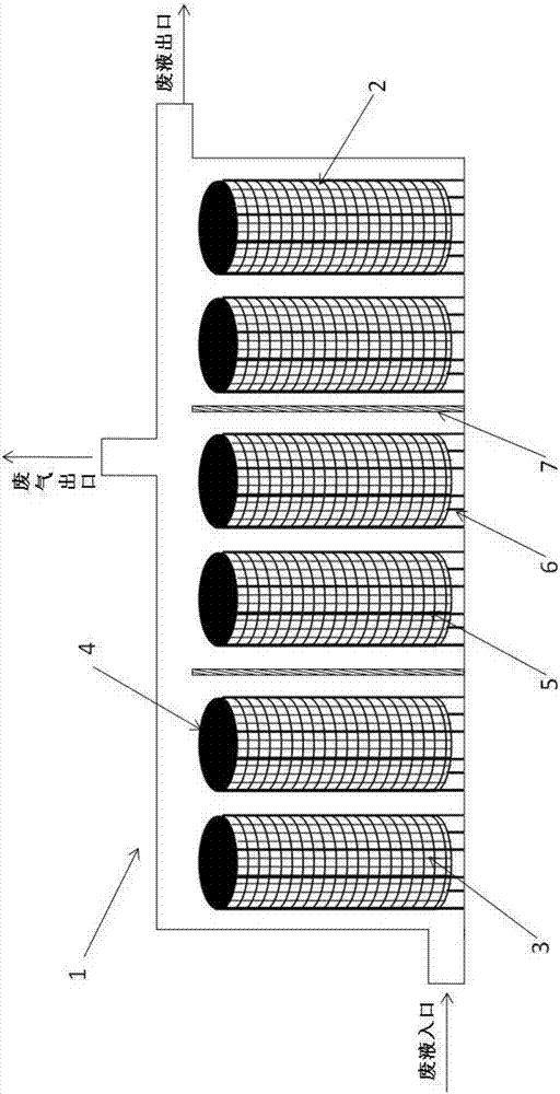
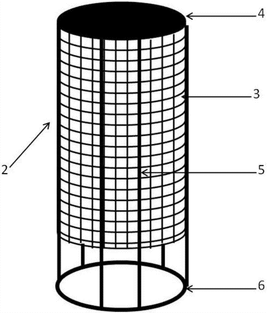
[0023] like figure 1 As shown, a waste liquid treatment device includes a reaction chamber 1, a waste gas outlet is provided on the top wall of the reaction chamber 1, and a waste liquid inlet and a waste liquid outlet are respectively provided at both ends of the reaction chamber 1, wherein the waste liquid inlet is arranged close to the reaction chamber. The bottom of the chamber 1, the waste liquid outlet is arranged on the top of the other end of the reaction chamber 1, and the waste liquid inlet, the waste liquid outlet and the exhaust gas outlet are all provided with on-off control valves; the reaction chamber 1 is fixedly provided with 3 catalytic treatment units, each catalytic The processing unit is provided with two catalyst-carrying tube bundles 2 , and the catalyst-carrying tube bundles 2 are fixedly distributed in the reaction chamber 1 in parallel and spaced apart. A baffle plate 7 is arranged between the catalyst processing units, the baffle plate 7 is fixed at ...


PUM


Abstract

The invention belongs to the technical field of waste liquid disposal and relates to a waste liquid disposal device applying an environment-friendly physical material. The device includes a reaction chamber, a waste gas outlet is formed in the top wall of the reaction chamber, and meanwhile the two ends of the reaction chamber are provided with a waste liquid inlet and a waste liquid outlet respectively; at least one catalyzation treatment unit is fixedly arranged in the reaction chamber, and at least one catalyst loading tube bundle is arranged in the catalyzation treatment units; the tube walls of the catalyst loading tube bundles are made of hard net structures, the net structures are coated with fiber active carbon layers soaked in catalysts or containing the catalysts, the inlet endsof the catalyst loading tube bundles are formed in the bottom, and sealed covering plates for preventing the liquid from passing through are arranged on the top. The sealed covering plates of the catalyst loading tube bundles are made of materials capable of preventing the liquid from passing through. The waste liquid disposal device is simple in structure, easy to manufacture and applicable to demands for large-scale or small-scale waste liquid disposal and has great popularization usability.

Description

technical field [0001] The invention belongs to the technical field of waste liquid treatment, relates to the technology of making a waste liquid treatment catalyst loading device by applying environment-friendly physical materials, and in particular relates to a waste liquid treatment device. Background technique [0002] Waste liquid treatment usually adopts the catalytic decomposition method, because this method does not have problems related to chemicals, by-products, etc., and the reaction proceeds relatively quickly. However, when the catalyst exists in a particulate state, the small specific surface area of ​​the catalyst will inhibit the improvement of the treatment efficiency, and when the gas is generated in the decomposition reaction of the waste liquid components, the reactor must have a channel structure in order to allow the gas to be discharged from the system To guide the upward flow of waste liquid, this situation is prone to catalyst wear and loss. [0003...

Claims


Application Information

Patent Timeline
Patent Type & Authority Applications(China)
IPC IPC(8): B01J8/06C02F1/00
CPCB01J8/0423B01J8/06C02F1/00C02F2201/002C02F2301/08
Inventor 周莉
Owner 大连百达开成不动产咨询有限公司
Why Eureka
Try Eureka