
Impurity removal mechanical equipment with drying function for metallurgical mining

A technology of drying function and mechanical equipment, applied in dryers, drying gas layout, lighting and heating equipment, etc., can solve the problems of poor screen filtering effect, long time required, and impurity removal mechanism screening, etc. The effect of reducing labor intensity and improving work efficiency

Inactive Publication Date: 2018-05-08
洛阳高昌机电科技有限公司
View PDF0 Cites 8 Cited by
  • Summary
  • Abstract
  • Description
  • Claims
  • Application Information

AI Technical Summary

Problems solved by technology

[0003] There is no drying device installed on the impurity removal machine used in existing metallurgical mines. The mined ore contains a certain amount of water, and the impurities and metal compounds are bonded together, which cannot be screened out by the impurity removal mechanism. In addition, there is no cleaning mechanism installed inside the existing metallurgical mine development equipment for removing impurities. When impurities or metal compounds are stuck or attached to the screen, the filtering effect of the screen is poor, requiring staff to disassemble the equipment and manually clean it. Cleaning the screen is cumbersome and takes a long time, and the labor intensity of the staff is high

Method used


Image

  • Impurity removal mechanical equipment with drying function for metallurgical mining
  • Impurity removal mechanical equipment with drying function for metallurgical mining
  • Impurity removal mechanical equipment with drying function for metallurgical mining

Examples


Embodiment Construction

[0019] In order to make the technical means, creative features, goals and effects achieved by the present invention easy to understand, the present invention will be further described below in conjunction with specific embodiments.

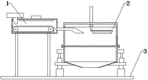
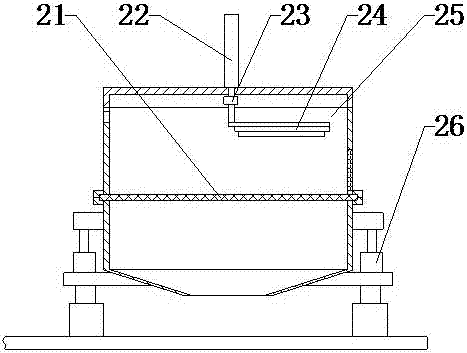
[0020] see Figure 1-Figure 3 , the present invention provides a technical solution: a metallurgical mine with a drying function for removing impurities mechanical equipment, including a heating mechanism 1, a cleaning mechanism 2 and a bottom plate 3, the heating mechanism 1 is installed on the left end of the cleaning mechanism 2, the heating mechanism 1 and The cleaning mechanism 2 is installed on the upper end of the base plate 3 .

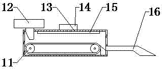
[0021] The heating mechanism 1 includes a conveyor belt 11, a feeding funnel 12, a box body 13, a heating fan 14, an exhaust pipe 15, and a feeding pipe 16. The feeding funnel 12 is installed on the upper end of the box body 13 and extends to the inside of the box body 13. The heating blower 14 is arranged on the...


PUM


Abstract

The invention provides impurity removal mechanical equipment with a drying function for metallurgical mining. The impurity removal mechanical equipment comprises a conveying belt, a box body, a heating fan, an exhaust pipe, a sieve screen, an electric cylinder, a servo motor, a cleaning brush, an impurity removal box and a vibration mainframe, wherein the heating fan is installed at the upper endof the box body; the exhaust pipe is arranged at the top end in the box body; the heating fan penetrates through the box body and is connected with the exhaust pipe; and a conveying belt is arranged in the box body. Due to the design, the function of heating drying is realized; the electric cylinder is installed at the upper end of the impurity removal box and extends into the impurity removal box, a servo motor is arranged at the lower end of the electric cylinder, the cleaning brush is installed at the lower end of the servo motor, the sieve screen is arranged at the lower side of the cleaning brush, the servo motor, the cleaning brush and the sieve screen are all installed in the impurity removal box, and the vibration mainframe is installed at the lower end of the impurity removal box;due to the design, a cleaning function is realized; and the impurity removal mechanical equipment provided by the invention is convenient to use, has the heating function, improves the impurity removal effect, and lowers the labor intensity of working personnel.

Description

technical field [0001] The invention relates to a metallurgical mining mining impurity removal mechanical device with a drying function, which belongs to the technical field of mining. Background technique [0002] Metallurgy is the process and technology of extracting metals or metal compounds from ores, and using various processing methods to make metals into metal materials with certain properties. Metallurgy has a long history of development in my country, from the Stone Age to the subsequent Bronze Age, and then To the large-scale development of modern iron and steel smelting. The history of human development incorporates the development of metallurgy. After mining the ore, the staff need to use impurity removal machinery to conduct preliminary screening of the ore to realize the impurity removal function. [0003] There is no drying device installed on the impurity removal machine used in existing metallurgical mines. The mined ore contains a certain amount of water, ...

Claims


Application Information

Patent Timeline
IPC IPC(8): B07B1/28B07B1/42B07B1/46B07B1/52F26B21/00
CPCB07B1/28B07B1/42B07B1/46B07B1/524F26B21/00
Inventor 邬宏敏
Owner 洛阳高昌机电科技有限公司
Learn More